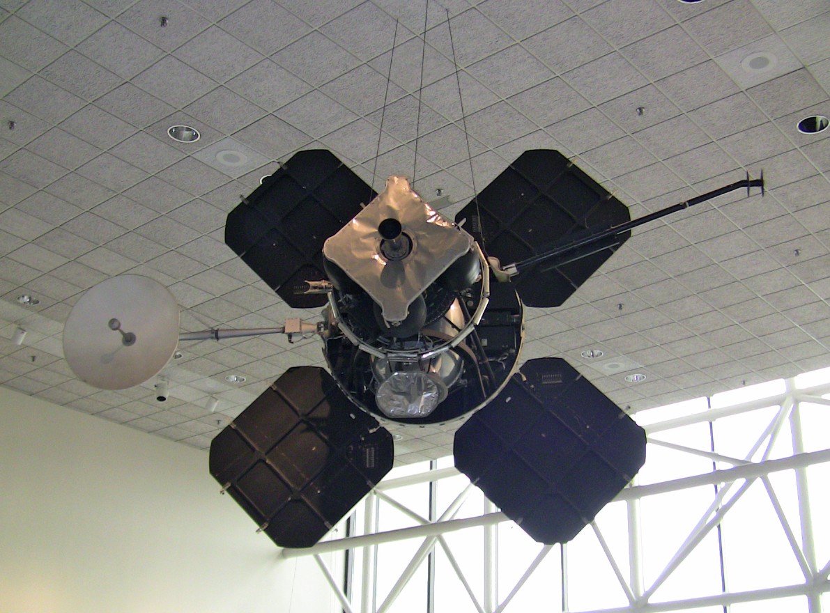
A Lunar Orbiter engineering mockup hangs in the National Air and Space Museum in Washington, DC.
Lunar Orbiter
August 1966 – January 1968
by Hamish Lindsay
Before Surveyor and Apollo, the question was, what is the Moon made of?
Would it support a spacecraft?
What if it was made of fine powder which would swallow a whole spacecraft?
What if it was made of a brittle foam rock that would be crushed by a spacecraft landing on it?
What if the surface was honeycombed with caves just under the surface for the spacecraft to fall into?
These questions had to be answered before trusting to put a manned spacecraft down on the lunar surface.
With Ranger and Surveyor, the Lunar Orbiter program was part of three complementary programs to survey the Moon’s surface and answer these questions, as well as select sites for the Apollo manned landings.
First, nine Ranger spacecraft headed straight for the lunar surface, taking TV pictures until impact on selected areas, with the last frame to main object of interest. After sending 17,000 pictures back to Earth, the Ranger program ended in March 1965.
Then, headed by geologist Eugene Shoemaker, the Surveyor series of soft landings on the Moon’s surface ferreted out the properties of the lunar surface, and found it was hard enough to support a spacecraft. 88,000 high-resolution pictures were taken by the seven Surveyor spacecraft, and the soil sampled with three chemical analyses. The last Surveyor signal was received on 10 January 1968.
THE LUNAR ORBITER PROGRAM GETS UNDER WAY.
The Lunar Orbiter program began in June 1962 when NASA’s Office of Manned Space Flight submitted a formal list of requirements for data of the Moon’s surface to choose the Apollo landing sites. The list gave the Office of Lunar and Planetary Programs its first opportunity to compare the objectives of its lunar programs with preliminary Apollo needs. It re-examined the mission objectives of the Surveyor Lander and acknowledged that Ranger data alone would not meet the Apollo requirements.
NASA selected a design proposed by The Boeing Co. of Seattle, Washington. Although this choice was criticized because it involved a relatively complex and costly camera and spacecraft configuration, NASA Headquarters was convinced that the Boeing design was the one that would best meet the requirements of the mission.
|
A Lunar Orbiter engineering mockup hangs in the National Air and Space Museum in Washington, DC. |
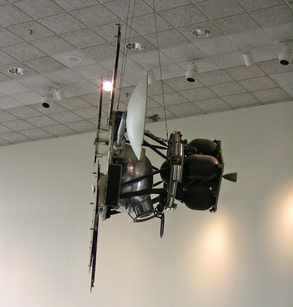 |
Side-on view of the Lunar Orbiter mockup in the NASM. |
Five Lunar Orbiter missions were launched from 1966 to 1967; all were successful. 99% of the Moon’s surface was photographed with a resolution of 60 metres or better.
The first three missions were dedicated to imaging 20 potential lunar landing sites, selected from Earth-based observations. These were flown at low inclination orbits. The fourth and fifth missions were devoted to broader scientific objectives and were flown in high altitude polar orbits. Lunar Orbiter 4 photographed the entire nearside and 95% of the farside, and Lunar Orbiter 5 completed the farside coverage and acquired medium (20 metre) and high (2 metre) resolution images of 36 pre-selected areas.
A total of 1,950 photographs were taken, and some 40 candidate sites for Surveyor and Apollo landings were identified. Models for study were made from the images of the lunar surface.
An initial elliptical orbit of 193 kilometres by 1,850 kilometres was chosen so the spacecraft would spend more time in the sun to make maximum use of solar power, and reduce the amount by which the velocity of the spacecraft would have to be modified in the manoeuvres near the Moon. Then the Orbiters were sent into low orbits to take sharp, close-up pictures of the lunar surface. They also supplied information on the Moon’s size, shape, gravitational field, micrometeoroid impacts, and radiation.
The greater part of the photography was done near perilune to achieve a balance between the required photographic resolution and to cover the maximum area. The Sun’s illumination of the ground had to be taken into account to bring out details by the use of shadows and highlights. The optimum sun angle was determined to be 10° to 30° above the local horizon. Sunrise, rather than sunset, was selected for photography so the spacecraft was travelling into sunlight to recharge the batteries to supply the power for processing the film after shooting.
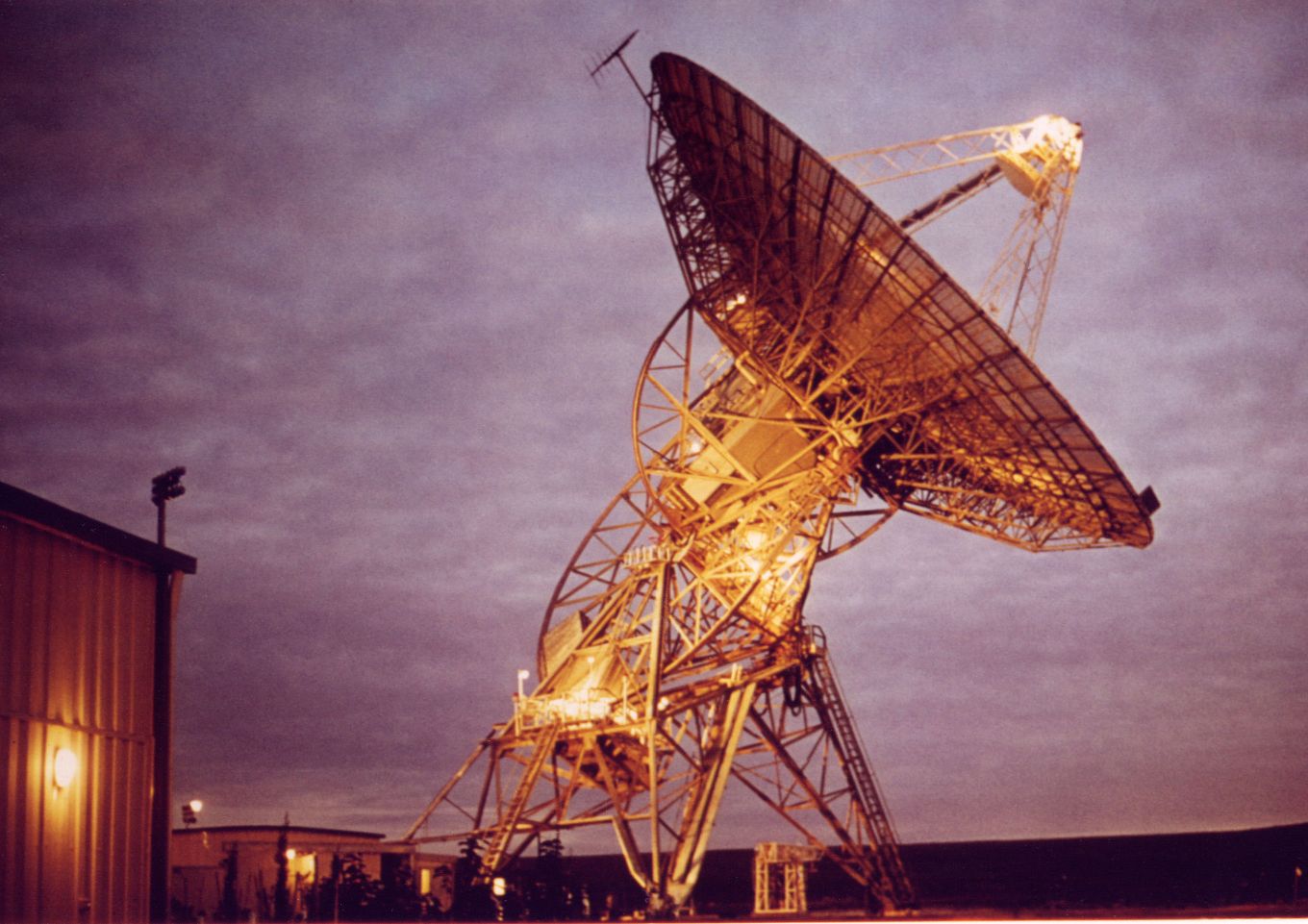
Honeysuckle Creek Station Director Don Gray has memories of Lunar Orbiter at DSS41, Island Lagoon,
When we first became operational at Honeysuckle Creek in 1967
we often used the Lunar Orbiters for tracking experience and engineering exercises
such as adjusting the antenna sub-reflector. We were never scheduled to track
the Lunar Orbiters for recovering data; that was the role of the Deep Space
Network, with Australia’s 26 metre diameter antennas at DSS41, Island Lagoon,
in the desert at Woomera, a prime site for the mission. DSS 42 at Tidbinbilla
was also scheduled to track the Orbiters.
 |
|
DSS41, Island Lagoon, near Woomera. Photo: Ed von Renouard. |
SUMMARY OF THE LUNAR ORBITER MISSIONS.
Lunar Orbiter I
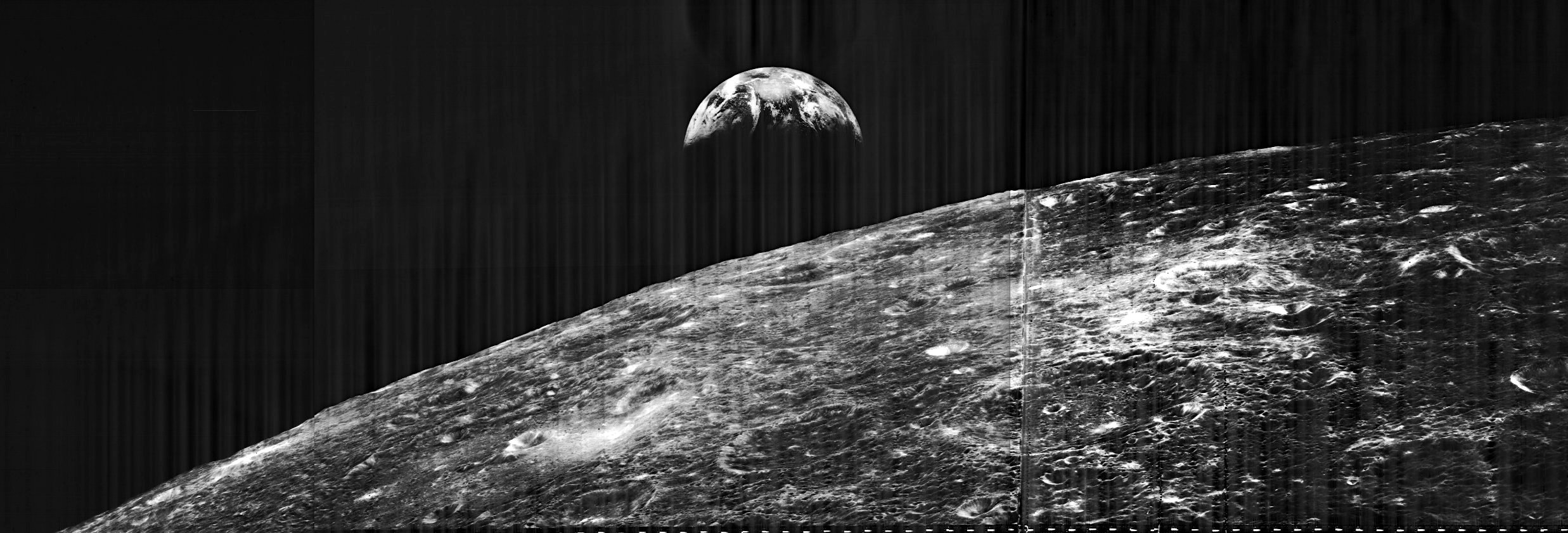
Lunar Orbiter I took the first remote images of the Earth from
the Moon on 23 August 1966.
 |
|
Lunar Orbiter I was launched from Cape Kennedy on 10 August 1966. |
Lunar Orbiter I was launched from Cape Kennedy Launch Complex 13 at 1526 EDT on 10 August 1966, the Atlas-Agena D launch vehicle injecting the spacecraft into its planned 90-hour trajectory to the moon. A midcourse correction manoeuvre was made at 2000 the next day. A faultless de-boost manoeuvre on 14 August achieved the desired initial elliptic orbit around the moon, and one week later the spacecraft was commanded to make a transfer manoeuvre to place it in a final close-in elliptic orbit of the moon.
During the photo-acquisition phase of the flight from 18 to 29
August, Lunar Orbiter I photographed the 9 selected primary potential Apollo
landing sites, including the one in which Surveyor I landed; 7 other potential
Apollo landing sites; the east limb of the moon; and 11 areas on the far side
of the moon. It also took photos of the Earth, giving man the first view of
Earth-rise from the Moon.
 |
|
Earthrise from Lunar Orbiter I. Courtesy Lunar and Planetary Institute. |
A total of 207 frames (sets of medium- and high-resolution pictures) were taken, 38 while the spacecraft was in initial orbit, the remainder while it was in the final close-in orbit. Lunar Orbiter I achieved its mission objectives, and, with the exception of the high-resolution camera, the performance of the photo subsystem and other spacecraft subsystems was outstanding. At the completion of the photo readouts, the spacecraft had responded to about 5,000 discrete commands from the Earth and had made about 700 manoeuvres.
There were some problems with the Bimat system. There was some image imperfections when a partial dry-out of the Bimat web was caused by a pressure variation of a roller resulted in a strip of incorrectly processed film, and some smearing of high-resolution images was caused by inadvertent triggering of the focal plane shutter of the telephoto lens.
Lunar Orbiter II
Less than three months elapsed between the launch of the first Orbiter and that of Lunar Orbiter II. On 6 November 1966 the second mission began, with the launch of the spacecraft at 1821 USEST. Lunar Orbiter II commenced its photographic work on 18 November and two days later it photographed the impact point of Ranger VIII.
On 23 November it recorded one of the most spectacular pictures of the lunar surface ever seen, billed as the ‘Picture of the Century.’ The picture of the Crater Copernicus was taken as a result of the threat of the Bimat film sticking and the need to move new film onto the processor drum at regular intervals. See below for an explanation of the Bimat system of film processing.
A certain amount of the film would be wasted if no exposure were made and a choice arose as to the use of this “film-set” frame. One mission ground rule called for the frames to be used to take pictures of any areas in the Apollo zone of interest, should the spacecraft be over one at the time. On the other hand, Douglas Lloyd of Bellcomm, Inc., had suggested during mission planning that this particular “film-set” frame be used to take a photograph of the crater Copernicus when the spaceraft passed due south of it at a distance of 240 kilometres and a vertical altitude of 45 kilometres above the lunar surface. Twice his suggestion was turned down by NASA officials because of the Apollo ground rule. However, upon Lloyd’s third suggestion program officials consented, and the decision to make the picture came during actual mission operations.
The Orbiter’s camera made a dual wide-angle/telephoto exposure,
and the 610 mm telephoto image of the crater from a long, low, oblique angle
to the lunar surface when lighting conditions were optimum for best contrast,
was chosen. The resulting picture revealed geographic and topographic features
of the central portion of this 100 kilometre-wide crater which had never been
seen before. On the horizon, behind the ledges and crater rim, the Gay-Lussac
Promontory in the Carpathian Mountains could be seen towering 1,000 meters above
the lunar surface.
 |
|
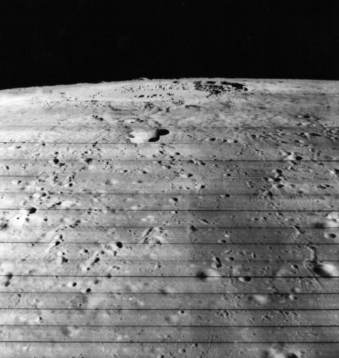
An oblique view from a distance of the Crater
Copernicus by It was taken with the wide-angle lens at 1905 USEST on 23 November 1966 when the spacecraft was 45.7 kilometres above the lunar surface and 240 kilometres south of the crater. Crater Copernicus, 96 kilometres in diameter and 3.2 kilometres deep, was formed by a giant meteorite. The rim of the crater is surrounded by angular blocks up to 46 metres across, while strings of small craters seen in the foreground were formed by the impact. 53 kilometres south of Copernicus is Fauth, the double crater in the middle foreground. It is about 21 kilometres long by 1.4 kilometres deep. |
|
|
|
A close-up of Copernicus Crater taken at the same time as the previous photo, on 23 November 1966 by Lunar Orbiter II. Called by the media the “Picture of the Century,” it is looking in the same direction, to the north, but the telephoto lens has changed the whole atmosphere of the crater. Now the frame is filled with a forbidding landscape of plunging cliffs, sweeping escarpments, and tumbling landslides backed by desolate mountain ranges rolling away into the distance. Ringed by rugged 600 metre high cliffs, a jagged mountain ridge thrusts up from the crater floor to a height of 305 metres. This view must have awed the Apollo astronauts, about to embark on their voyages to the Moon. In fact, this is the crater that was supposed to be the destination of Apollo 20, the last Apollo mission, as a spectacular finale of the Moon landing program. One suggestion was for the astronauts to fly a small spacecraft to the ledges of the surrounding cliffs. It’s a pity it was cancelled – it would have been an exciting mission. |
The status report of the Lunar Orbiter II mission as of 28 November 1966 indicated that the first phase of the photographic mission was completed when the final photo was taken on the afternoon of 25 November. On 26 November, the Bimat developing web was cut with a hot wire in response to a command from the earth. Failure to achieve the cut would have prevented the final readout of all 211 photos. Readout began immediately after the cut was made. One day early, on 6 December, the readout terminated when a transmitter failed, and three medium-resolution and two high-resolution photos of primary site 1 were lost. Full low-resolution coverage of the site had been provided, however, and other data continued to be transmitted.
Lunar Orbiter II had sufficient attitude control gas to survive until early November 1967. Ground control operators planned to impact it into the Apollo zone on the Moon’s surface, even though analysis of tracking data indicated that it could probably remain in orbit one or two years longer. Once the spacecraft lost its attitude control gas, however, it would become a derelict in orbit, beyond the control of ground operations. Program officials decided to crash the spacecraft while they could, to avoid any potential communications interference in future manned missions. On 11 October 1967 the flight controllers sent commands to destroy Lunar Orbiter II by crash landing on the lunar surface.
Lunar Orbiter III
 |
|
The lunar far side and Tsiolkovsky. |
The flight controllers planned to lower Lunar Orbiter III’s apolune
to make its orbit as circular as possible for further training for Apollo tracking.
However, expiration of its gas meant it would have to be crashed, so on 9 October
1967, the final commands were transmitted to destroy Lunar Orbiter III by lunar
impact.
Lunar Orbiter IV
Last minute tests did not reveal any problems of a magnitude serious enough to delay a launch, and at 1825 USEDT on 4 May Lunar Orbiter IV rode into space from Launch Complex 13 at Cape Kennedy. In its sixth orbit around the Moon the spacecraft began its first photographic pass at 1146 USEDT on 11 May.
Despite this apparent success, the spacecraft had already developed a serious problem which threatened to jeopardize the whole mission. Telemetry data indicated that after the second set of four frames had been exposed, the camera thermal door failed to close until ground control had sent additional commands to close it. After the third set of four frames had been made, spacecraft telemetry did not confirm if the door had opened sufficiently. Flight controllers initiated a preliminary corrective action by commanding the door to open far enough in advance of the fourth set’s exposure time to allow for additional commands if required.
Lunar Orbiter IV photography had covered 99% of the Moon’s near side at a resolution exceeding by ten times the best Earth-based telescopic photography.
The flight controllers had lost communications with Lunar Orbiter IV on 17 July 1967, and assumed that its orbit had decayed sufficiently to permit it to crash onto the Moon on 6 October 1967.
Lunar Orbiter V
Scheduled for 1609 USEDT 1 August 1967, the launch of Lunar Orbiter V was the cause of high anxiety for a while when a heavy rain storm held up the proceedings for two and a half hours. The launch window for 1 August only lasted from 1600 to 2000. A postponement until the following day was serious because it would mean the loss of some far-side photography. The Moon rotates 13° of arc on its axis per Earth-day, so a delay of one day would mean the loss of a 13° portion of the lunar far-side to darkness.
Fortunately the weather improved, and the countdown resumed to send Lunar Orbiter V on its way at 1833 USEDT. Photography commenced at 1922 on 6 August. At one stage Lunar Orbiter V was manoeuvred to reflect sunlight from its solar panels and underside mirrors with the reflected rays to be photographed by telescopes on Earth.
The photographic mission ended on 18 August when the spacecraft took its last photograph and ran out of Bimat film at 2320 USEDT. In all it had successfully covered 5 Apollo sites, 36 science sites, 23 previously un-photographed areas on the lunar far side, and a view of the nearly fully illuminated Earth.
Lunar Orbiter V began its extended mission late in August. Its orbit would be changed on 10 October so that it might better survive the umbral eclipse of 18 October so the spacecraft would pass through the eclipse and solar occultation by the Moon at the same time.
Apollo tracking stations continued to track the spacecraft as long as possible to increase their experience in preparation for manned lunar missions.
Lunar Orbiter V continued to fly an extended mission until it experienced an unexpected anomaly, which threatened its safety. A sudden loss of pressure in the nitrogen tank forced flight controllers to destroy the spacecraft prematurely on the Moon to avoid losing it in orbit. They conducted this final manoeuvre on 31 January 1968, bringing it down near the equator on the Moon’s western limb.
The destruction of Lunar Orbiter V brought the operational phase
of the Lunar Orbiter Program to a close, and ended one of the most successful
projects ever run by NASA.
The Spacecraft.
 |
|
Diagram of the Lunar Orbiter spacecraft. |
Built by the Boeing Aircraft Company and managed by NASA’s Langley Research Center, Hampton, Virginia, the Lunar Orbiter spacecraft weighed 385 kilograms. They were 1.7 metres tall and 1.5 metres in diameter at its base, without including the solar panels and the antennas. With its solar panels and antennas extended, the spacecraft measured 3.7 metres across the panels and 5.6 metres to the ends of the antennas.
The spacecraft consisted of two sections:
The Main Equipment Deck with the camera system, radiation detectors, communication and orientation equipment. Two antennas poked out on opposite sides of the spacecraft, a high-gain dish antenna and a low gain omni antenna.
The Upper Module housed the propulsion system, which included a 45 kilogram thrust liquid propellant rocket engine, and nitrogen gas jets for attitude changes. Storage tanks for fuel were also mounted on this module.
Electrical power was supplied by four solar arrays delivering 375 watts from 10,856 n/p solar cells which would directly run the spacecraft, and also charge the 12 ampere hour nickel-cadmium battery, used for Sun occultation periods.
The attitude control subsystem served as the navigator for Lunar Orbiter during an entire mission. Composed of Sun sensors, the Canopus sensor, the inertial reference unit, and the thrusters, the system controlled the spacecraft’s attitude in space using the Sun, the star Canopus, and the Moon as references. The sun sensor was used to control pitch and yaw of the spacecraft, while the Canopus sensor controlled roll. When these were not visible, stability was provided by three gyroscopes.
Receiving and transmitting data to and from the spacecraft was the job of the communications subsystem, many of whose components had been flight-proven in the Ranger and the Mariner programs. This complex assembly could operate in four individual modes:
The communications system could send and receive data simultaneously while also transponding velocity (doppler) and ranging signals for the Deep Space Network’s tracking and ranging systems.
The Lunar Orbiter Photographic System.
 |
|
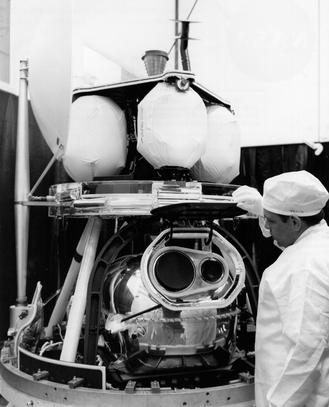
Lunar Orbiter’s camera lens assembly. |
Unlike the Ranger and Surveyor spacecraft, which transmitted images in real time, the Orbiters had a built-in film processing laboratory invented by Eastman Kodak called the Bimat process. This system did away with a cumbersome television payload and used a film system instead. Film had an advantage over the television of those days as far as its ability to obtain higher resolution photographs.
Besides eliminating the need for liquids and their storage containers, the Bimat system did away with the necessity of an extra fixing step while producing photographic negatives having normal, high-quality physical and image characteristics. This greatly simplified the problems involved in materials handling while making the whole process fully automatic. Moreover, every part of the film enjoyed fresh chemicals, which made the resulting negatives more consistent and uniform. Bimat would not leave any crystalline deposit on the film after separation, and lamination of the two materials would not result in any damage to the emulsion layer. In addition, the position of the equipment would not affect processing of the film, a factor which made the Bimat process ideally suited to work in a space environment.
The Orbiter photographic system was built by Eastman Kodak, and used a dual lens system to focus the images on to a single roll of 70 mm film with room for 212 dual frames. It was a 79- metre length of unperforated Kodak special high-definition aerial film, Type SO-243, with a very slow aerial exposure index of 1.6. It was extremely fine grained with a high resolving power, and highly resistant to fogging at the levels of radiation expected in space. The film storage cassette was specially shielded against ionising radiation from solar flares. Along one edge of the film was a thin band of pre-exposed data containing calibrated resolving power charts and grey scales which were read out with each image for later comparison and interpretation, as well as helping estimate slope angles of the lurain from measuring film densities.
The camera lenses viewed the lunar surface through a quartz window that was protected by a lifting flap opened by a command from the Earth for each photographic pass. The German Schneider Xenotar wide-angle lens had a focal length of 80 mm with a fixed aperture of f5.6 and a between-lens shutter giving 1/25, 1/50 or 1/100 second exposures. The 610 mm telephoto lens was a f5.6 Paxoramic specially designed and made for the spacecraft by Pacific Optical Company. Weighing less than 7.3 kilograms, it had its own focal plane shutter offering the same exposure times as the wide-angle shutter. The two shutters operated simultaneously, so each exposure produced two images, the telephoto lens taking about 5% of the area of the wide angle lens, but at a resolution 8 times better.
For example at an altitude of 46 kilometres the wide-angle lens covered an area of 31.5 kilometres by 37.3 kilometres with a resolution of 7.3 metres. In the centre of the same footprint the telephoto lens covered an area of 4.2 kilometres by 16.4 kilometres with a resolution of 0.9 of a metre. To cover larger areas photographs were overlapped, either by successive exposures along the flight path, or on successive orbits. Stereoscopic pictures could be produced if required, for instance to determine the slope of a hillside.
With the spacecraft speeding over the lurain at 6,920 kilometres per hour, taking pictures at around the perilune regions with shutter speeds of 1/25, 1/50, or 1/100 of a second dictated by the slow film speed, would result in blurred images, so there was a mechanism to compensate for the motion. It sensed the velocity to height ratio of the spacecraft by measuring the apparent motion of a small portion of the lunar surface viewed through the telephoto lens, and applied the necessary corrections to the speed of the film past the aperture during exposure.
The exposed film was developed using the Bimat technique invented
by Kodak. Housed in a pressurised and temperature controlled unit, the process
pressed the exposed film against a web, or roll with a gelatine layer that had
been soaked in a solution that developed and fixed the film in one step. The
film was then dried by passing it over a heated drum, before being fed into
a flying-spot scanner to be read a frame at a time. Here the image could be
converted to electronic signals by the scanner upon command from the ground,
then the film stored on to a take-up reel. The line-scanning device consisted
of a cathode-ray tube with a rotating anode having a high-intensity spot of
light. One complete scan, or raster, took up 2.54 millimetres of film and the
full 60 millimetres width, these being the strips visible in the pictures. This
process was repeated 286 times for each millimetre of film scanned. It took
a 5 micron light beam 22 seconds to do 17,000 horizontal scans to produce one
band of an image.
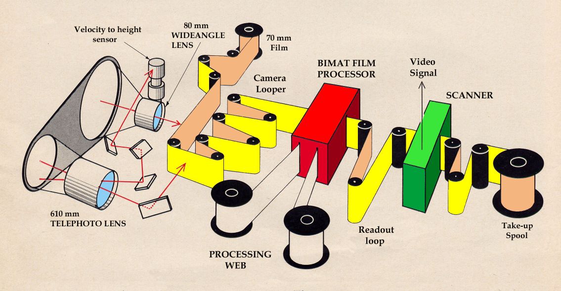 |
|
The Bimat system used on Lunar Orbiter. |
Photographic data was transmitted in a different way to telemetry data. The spacecraft had two antennas that operated in the S-band at the frequency of 2295 Mhz. When photographic data was transmitted to the tracking stations, the spacecraft operated in the high-power mode, and transmitted the signal via the 1 metre diameter parabolic high-gain antenna. Simultaneous transmission of photographic and telemetry data was carried out as follows:
The 50-bit/second telemetry data train was phase modulated onto
a 30khz subcarrier, which was then combined with the video data that had been
transformed to a vestigial sideband signal. That signal was created by amplitude
modulating the data on a 310khz subcarrier by means of a double balanced modulator.
This suppressed the carrier and produced two equal sidebands. An appropriate
filter was then superimposed on the double sideband spectrum, essentially eliminating
the upper sideband.
Since the missing subcarrier must be reinserted on the ground for the proper
detection of the vestigial sideband signal, provision for deriving such a subcarrier
signal was made by transmitting a pilot tone of 38–75khz. That pilot tone
was exactly one-eighth of the original 310khz subcarrier frequency, and was
derived from the same crystal oscillator. Multiplying the received pilot tone
by 8 in the ground equipment provides a proper subcarrier for reinsertion.
Lunar Orbiter photographic data was never encoded; instead, data was transmitted
as frequency-modulated analog signals. All other data from the spacecraft were
encoded and sent on the subcarrier frequency as described above.
The temperature control subsystem protected all of the spacecraft’s other subsystems from the extreme temperature variations of the deep space environment. Heat from the Sun could warm external parts of the spacecraft to 120°C while areas not exposed to solar radiation would cool down to -160°C. These extremes were beyond the temperature levels most components could endure. The temperature control system established an environment ranging from + 2°C to +30°C for the operation of all subsystems. A few components were exposed to direct sunlight: the four solar panels, the two antennas, and the bottom of the equipment deck. The solar panels were designed to withstand temperature variations of 160°C to +120°C without cracking or buckling from severe expansion and contraction over a long period of time.
PROGRAM SUMMARY.
To summarise the achievements of the Orbiter Program; Lunar Orbiter II photography led to the identification of the Ranger VIII impact point on the Moon. The locations of all the Surveyor spacecraft were determined by Orbiter photography. The fifth Orbiter had photographed major lunar features of scientific interest at a resolution 100 times better than Earth-based telescopes could achieve under ideal observation conditions. The Orbiters photographed the entire lunar surface at a better resolution by at least an order of magnitude than Earth-based telescopes could attain, and surveyed the heavily cratered far side of the Moon. Tracking the spacecraft’s orbits yielded improved data on the Moon’s overall shape and gravitational field. Maps were produced of the lunar surface from the Orbiter photography.
Altogether the Orbiters returned 2180 high resolution images of the surface of the Moon (near and far side) with resolution down to 1 metre, and 882 medium resolution frames. The micrometeoroid experiments recorded 22 impacts showing the average micrometeoroid flux near the Moon was about two orders of magnitude greater than in interplanetary space, but slightly less than the near Earth environment. The radiation experiments confirmed that the design of Apollo hardware would protect the astronauts from average and greater-than-average short-term exposure to solar particle events.
The use of Lunar Orbiters for engineering evaluation and training station personnel of the Manned Space Flight Network as well as the Apollo Orbit Determination Program, was very successful, preparing the stations for the manned lunar missions beginning with Apollo 8 in December 1968. Three Lunar Orbiters (2, 3, and 5) were tracked simultaneously from August to October 1967.
The tracking stations could not have obtained the tracking experience in the lunar environment at a timely date if NASA had not flown the five Lunar Orbiter spacecraft.
Unless noted, all photographs courtesy NASA. The diagrams are by NASA, enhanced by Hamish Lindsay.
