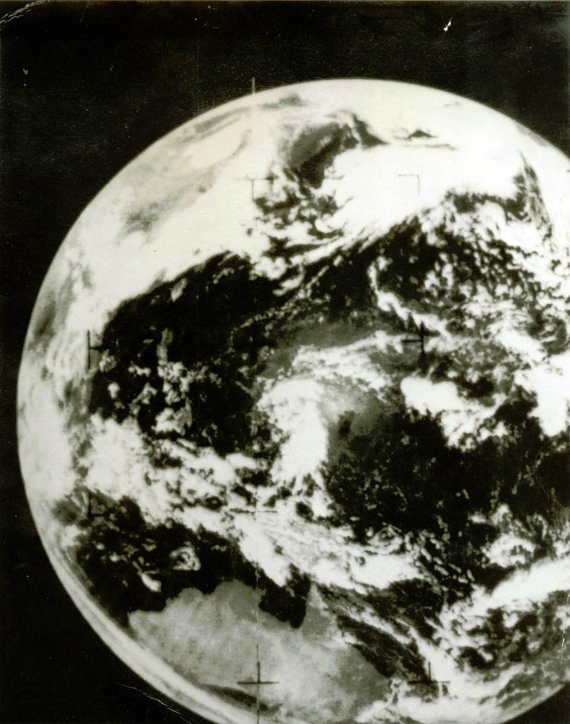
Australia from ATS-2.
Cooby Creek Techical Description
by Ken Anderson
Cooby Creek Tracking Station was located on the banks of the Cooby Creek dam, 22.5 km north of Toowoomba, Queensland, Australia. [Approximately 27 Degs 23 Mins 26 Sec S, 151 Degs 56 Min 28 Sec E]
This station, known as the TRANSPORTABLE GROUND STATION [TGS], was installed in 1966 to support NASA’s Application Technology Satellite Program [ATS], and was a part of the Spacecraft Tracking and Data Acquisition Network. The Applications Technology Satellite program grew out of a proposed Advanced SYNCOM project, and integrated a number of experiments into the one program. The ATS project involved the projected launch of 6 experimental communications satellites which were to be used to carry out tests of various techniques which might be used with such satellites.
Three ground stations were used in this project, in addition to the TGS they were located at –
Rosman, North Carolina. This station employed a 26 metre [85 ft] XY mounted parabolic antenna for the main communications experiments as well as a VHF Telemetry and Command [T&C] antenna. The station was located in the mountains above Rosman so as to be shielded from terrestrial sources of radio frequency interference. The site is now called the Pisgah Astronomical Research Institute [PARI].
(See the Facts about Rosman booklet, prepared for BFEC emplyees going to Rosman. Published 1972.)
Mojave, California, where a 12 metre XY mounted antenna and the VHF T&C antenna were employed. It was also the main station for the WEFAX experiments, in which Weather facsimiles were transmitted, via the VHF ransponder of the ATS satellites to station in the Pacific region
The TGS was equipped with a 12-metre [40 ft] Cassegrainian feed, Az-El mounted antenna which was used to receive and transmit the 4 GHz down link and 6 GHz up link signals, as well as with the VHF T&C antenna.
This station was packaged into 7 semi-trailers.
The first of these carried the disassembled 12 metre antenna, and included hydraulic lifting equipment which allowed the antenna, after the dish was assembled, to be hoisted onto the prepared concrete support base.
Two of the semi-trailers constituted the station power generation sub-assembly, each containing two gas turbine driven generators to provide the primary 208V 60Hz 3 Phase supply required. The generators provided a total of 750 k VA.
A third trailer contained the T&C sub-system, which transmitted commands to and received data from the several satellites.
The remaining three semi-trailers constituted the main operational area of the station. Two of these had one removable side whilst the third had both sides removable. With the sides removed they were positioned alongside each other so as to provide the required space. The joins between each of the trailers was covered by a rubber weather proof strip.
This area contained –
a. The exciter section of the 6GHz transmitter.
b. The IF portions of both the data and the antenna auto-track receivers.
c. The 12 metre antenna control console.
d. Control panel for cryogenic package for MASER and PARAMPS
e. The 120 channel telephone multiplex sub-system
f. The Operations Control Console.
g. The SDS910 general purpose computer.
h. The Communications Test Evaluation Console [CTEC]
i. The telephone channel echo-suppressors.
j. The Range and Range Rate system.
k. The station timing sub-system
l.. The AMPEX video recorder
m. The flying spot scanner.
Also included here was an administration area and maintenance bench space.
Construction and History
The TGS was built at the Sylvania plant in Waltham, Massachusetts. A team of Australian engineers and technicians had participated in the assembly, integration and final testing of the station, and on the completion of that process the station was shipped to Brisbane, Queensland. Australia.
Upon being unloaded from the ship the semi-trailers then went by road to the selected site on the banks of the Cooby Creek dam. It was operational for the launch, in December 1966, of ATS-1. This satellite a spin stabilized geo-synchronous, was successfully inserted into orbit and positioned over the Pacific Ocean.
The SHF receiver system employed a Low Noise Amplifier [LNA] comprising a MASER followed by two PARAMPS. These devices were cryogenically cooled by a liquid helium sub-system, which maintained the MASER at 4.2 K and the PARAMPS at 20 K. The MASER sub-system included a super-conducting electro-magnet which, by f Zeeman splitting, allowed adjustment of the MASER bandwidth. The effective bandwidth of the MASER, which employed three synthetic ruby strips some 75 mm long and their associated comb slow wave structures, was 130 MHz and that of the PARAMPS 200 MHz. The LNA could be operated in different modes, in mode 1 the MASER and PARAMPS were in series, whereas in mode 2 the MASER was bypassed and the PARAMPS alone provided the LNA function. The overall system noise temperature in mode 1 was approximately 70 K, or, a Noise Figure of 0.94 dB.
The helium liquefying compressors consumed some 10kW, the 4.2 kelvin station could maintain that temperature whilst dissipating approximately 3 watts.
The SHF Antenna auto-tracking system employed a pseudo-monopulse technique. The antenna feed comprised a 5 dielectric rod feed. The centre rod was the transmitter element working at 6 GHz. The receiver section, working at 4 GHz, had to rods mounted in the vertical plane and two in the horizontal plane. The vertical plane elements fed a comparator which derived a sum out put and a difference signal which gave the elevation error. Similarly, the horizontal elements were used to derive a sum out put and the azimuth error signal. The two sum outputs were combined as the sum and the two difference signals were multiplexed onto the sum signal. Arranged around it, 2 mounted in the vertical plane and 2 in the horizontal plane. Comparators used the signals from these horns to derive a sum signal and elevation and azimuth error signals. The error signals were multiplexed onto the sum signal. This technique allowed the error signals to be amplified by the one LNA. The composite amplified signal was down converted to 400 MHz and fed to the IF amplifiers in the main operational area. Synchronous demodulators there extracted the elevation and azimuth error signals and applied those signals to the Antenna servo system so that the system continuously remained on the spacecraft.
The antenna feed system also incorporated a polarization tracking system which automatically adjusted the polarization of the receiver horns so as to compensate for the the Faraday rotation of the plane of polarization during its transit from the spacecraft to the TGS antenna.
Experiments
Once ATS-1 was in orbit a series of tests were commenced. The control of the satellite rested with the ATS Operational Control Centre [ATSOCC] located at NASA headquarters in Washington D.C. Each of the three stations were in direct communications with ATSOCC and carried scheduled rests at the direction of that centre.
Two satellite modes were employed for these tests. One of these. The FM mode, allowed one station to utilize the entire bandwidth of the spacecraft transponder, and had the TGS SHF transmitter operating in FM. This would typically be used when a TV broadcast was being sent from one station to another, so, Cooby Creek was the Australian Earth Station for the “Our World” broadcast on 25 June 1967, the TGS then transmitted the Australian contribution to this program and, later, received the broadcasts from the various other countries for onward transmission to the Australian TV stations, all this in FM mode.
The second mode, called the Multiple Access [MA] mode allowed the three ground stations to share the spacecraft transponder bandwidth. In this mode the SHF transmitters employed the SSB mode of transmission.
This mode was employed when carrying out tests using the telephone multiplex system, when each station had to transmit and receive simultaneously so as to provide the duplex channels required for telephony. In this mode each ground station transmitted a pilot tone which was used to close a control loop so as to adjust each stations transmitted power in order to prevent any one station from “seizing” the entire transponder bandwidth.
The tests were largely automated, the SDS 910 computer controlled the test equipments located in CTEC, collected the data and recorded that data onto magnetic tape. After each test the tape and other documentation was mailed to ATSOCC. Prior to each test the station crew configured the equipment through patch panels, calibrate the equipment, and prepared the various documents required.
One of the experimental packages it carried was the Spin Stabilized Cloud Camera [SSCC]. A light sensor was located on the side of the satellite, and as the satellite rotated this sensor made a narrow scan of the earth. The sensor was stepped slightly fro the next rotation, and so on. The result of this process was that a photo of the earth was derived every 20 minutes. An early test using this system involved the continuous operation of the SSCC for a 24 hour period, resulting in 72 photographs of the cloud cover. A continuous loop of the sections covering Hawaii revealed the clouds forming at the peak of [presumably] Mauna Kea and streaming downwind from that point, a memorable demonstration of the dynamics of cloud formation.
Another experiment utilizing ATS 1 was the transmission, from the Mojave Ground Station, of meteorological maps etc to APT equipped stations in the USA, Canada, Australia, Japan, and the Pacific Islands via the spacecraft VHF transponder.
The advance in technology in less than 20 years is shown by the fact that, when Arthur C Clarke wrote his seminal article on Communications Satellites in 1948, the satellites would have had to be manned, given the reliability of the vacuum tube electronics then available. When ATS 1 was launched in 1966 its design life was 3 years – in fact the VHF communications system was still functioning until 1985, an effective life of 19 years.
The TGS supported the various ATS satellites, albeit that ATS 1 and ATS 3 and ATS6, were the only three successfully launched. However ATS 6 [which remained in service for 5 years] was launched on 30 May 1974 after the TGS had been de-activated.
The second stage rocket employed in the case of ATS 2 failed so the satellite did not reach its intended orbit.
In the case of ATS 4 the Centaur rocket failed and the satellite was in such a low orbit that atmospheric drag caused it to re-enter the atmosphere and burn up. It finally did re-enter in October 1968, and during its 14 month lifetime some of the experiments were switched on.
Memorably, for those of us at Cooby Creek, one of these produced a black and white photograph of the entire Australian continent. My memory of that photograph being received was someone’s comment, “Those early explorers got it right!”
|
Australia from ATS-2. |
ATS 5 failed, although it did reach its intended orbit, developing a wobble and ended up spinning in the wrong direction.
-----