GOLDSTONE DEEP SPACE COMMUNICATIONS COMPLEX
THE WORLDWIDE DEEP SPACE NETWORK
The Network staff in the United States consists of JPL engineering and technical personnel, assisted by contractor engineers and technicians who are primarily responsible for operating and maintaining the Goldstone complex, the Network Operations Control Center, and the Ground Communications Facility at JPL. The Spanish and Australian complexes are staffed and operated by agencies of the Spanish and Australian governments and their contractors. The total international staff includes over 1,100 people.

The Deep Space Communications Complexes are located at Goldstone, California; near Madrid, Spain; and near Canberra, Australia.
The DSN Complexes
Each of the three Deep Space Communications Complexes consists of four deep space stations equipped with ultrasensitive receiving systems and large parabolic dish antennas. At each complex there are two 34-meter (111-foot) diameter antennas, one 26-meter (85-foot) antenna, and one 70-meter (230-foot) antenna. A centralized Signal Processing Center remotely controls the 34- and 70-meter antennas, generates and transmits spacecraft commands and receives and processes the spacecraft telemetry.
The antennas form separate subnets according to size; each subnet has a different communications capability. The 70-meter antenna subnet, which is the most sensitive, supports deep space missions; the 26-meter subnet supports spacecraft in Earth orbit; and the two 34-meter subnets support both types of missions.
The 26-meter antenna stations were originally part of the Spaceflight Tracking and Data Network, which is operated by NASA's Goddard Space Flight Center, located in Greenbelt, Maryland. The Goddard network is designed to support the manned orbiting Shuttle flights and Earth-orbiting scientific and communications satellites. The 26-meter stations were consolidated into the Deep Space Network in 1985 when it assumed an important added tracking responsibility for spacecraft in high elliptical Earth orbits. This realignment was in anticipation of the activation of Goddard's new Tracking and Data Relay Satellite System, which is not compatible with spacecraft in "high" Earth orbits that travel out beyond the range of the new relay satellite system. This new satellite system will eventually replace nearly all of Goddard's ground stations, leaving the Deep Space Network as NASA's only ground-station network.
The Ground Communications Facility
The Ground Communications Facility provides and controls the communications circuits that link the three communications complexes to the control center at JPL and to the flight project control centers in the United States and overseas. The communications traffic between these locations is sent via land lines, submarine cable, terrestrial microwave, and communications satellites. These circuits are leased from common carriers by the NASA Communications Network, which is located at the NASA Goddard Space Flight Center, and are provided as needed to all of NASA's projects, centers, and facilities.
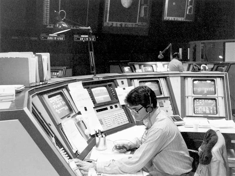
The Network Operations Control Center at JPL monitors and controls mission operations at the three complexes around the world.
The Network Operations Control Center
The Network Operations Control Center, which is the operations hub of the Network, is located at JPL in Pasadena. Its functions are to monitor operations at the three complexes, to validate the performance of the Network for flight project users, to provide information for configuring and controlling the Network, and to participate in Network and mission testing.
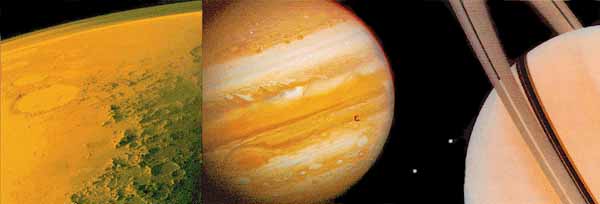
Photographs from space are formed by thousands of picture elements, which are scanned for brightness and assigned a number by the spacecraft computer. These numbers are transmitted to Earth and converted back into picture elements to form the photographs. Shown from left to right are Mars and its carbon dioxide atmosphere (Viking Orbiter 1, 1976), Jupiter and its moon Io (Voyager 1, 1979), and Saturn and its moons Tethys (top) and Dione (Voyager 1, 1980).
The Network's Mission Support
From 1958 through 1988, the Network provided principal tracking telemetry, and command support for 27 spaceflight projects involving a total of 68 Unmanned Earth orbiting, lunar, and planetary spacecraft. Moon exploration begun with the Pioneer 3 and 4 lunar probes (1958), followed by the Ranger 1-9 lunar TV probes (1961-65), the Surveyor 1-7 lunar landers (1966-68), and the Lunar Orbiter 1-5 photographic survey for Apollo landing sites (1966-67).
Support for inner-planet exploration began in 1962, with JPL's Mariner series of missions to Venus, Mars and Mercury, involving six planetary flyby missions and the first planetary orbiter at Mars (1971). Concurrent with the mariner flights were the NASA Ames Research Center Pioneer missions, beginning with the Pioneer 6-9 heliocentric orbiters (1965-68)
Support for the first outer planet missions, the Pioneer 10 and 11 flybys of Jupiter and Saturn, begun in 1972-73, and support for the Pioneer 12 and 13 Venus explorers was initiated in 1978. During the late 1960s and early 1970s, the Network also provided backup communications support for the manned Apollo missions to the Moon.
In the middle 1970s, the Network began support for the Helios 1 and 2 solar orbiters, a joint American-West German project to investigate the near-solar environment, and for the NASA Langley Research center's Viking 1 and 2 Mars orbiter and lander missions. In 1977, JPL's Voyagers 1 and 2 began their outer planet flyby missions to Jupiter (1979), Saturn (1980-81), Uranus (1986), and Neptune (1989).
During 1986-88, the DSN provided support to the following deep space and Earth-orbiting missions:
Pioneers 6 through 8. In heliocentric orbits between Venus, Earth, and Mars, Pioneers 6 through 8 are returning solar weather data. Pioneer 6, launched in December 1965, is the world's oldest operating spacecraft The signal from Pioneer 9 was lost in 1983.
Pioneers 10 and 11. These spacecraft are returning scientific duty from the previously unexplored outer edges of the solar system. Pioneer 10 will be the first Earth-made object to leave the solar system and enter interstellar space.
Pioneer 12. In Venus orbit, Pioneer 12 is returning Venusian atmospheric data The spacecraft observed Halley's comet in early 1986.
Voyagers 1 and 2. In January 1986, Voyager 2 encountered Uranus and was supported during the encounter with an international multi-station array. The Network is now planning for the Voyager 2 encounter with Neptune in 1989 and will eventually track both Voyagers beyond the solar system and into interstellar space.
Nimbus 7. This low-polar-orbit weather and pollution monitoring satellite was launched in 1978 and provides daily global observations of the Earth's atmosphere and its surface. Goldstone receives telemetry from the satellite during three or four 15-minute passes each day.
International Venus Balloon missions. The Venus Balloon Experiment involved two Soviet Vega spacecraft each carrying a French meteorological balloon that was inserted into the Venusian atmosphere as the two spacecraft passed the planet on their way to a flyby of Halley's comet. The Deep Space Network and an international array of 17 other antenna stations successfully tracked the balloons, providing information on the weather dynamics of the Venusian atmosphere.
Halley's Comet Flyby. The Network provided navigation support to five international spacecraft that encountered Halley's comet in March 1986. The Halley flyby involved Soviet Vega 1 and Vega 2 spacecraft Japanese Sakigake and Suisei spacecraft and the European Space Agency's Giotto spacecraft.
International Cometary Explorer. The Network maintained continuous communication with the Explorer as it passed through the tail of the Giacobini-Zinner comet in September 1985. Support was also provided by the Japanese Usuda Observatory and the National Astronomy and Ionosphere Center's Arecibo Observatory in Puerto Rico. The Network and Usuda continued support during the Explorer's observations of Halley's comet in December 1985 and March 1986. The Network continues to monitor the interplanetary travel of the spacecraft.
Active Magnetospheric Particle Tracer Explorers (AMPTE). AMPTE involved three spacecraft in Earth orbit that released barium and lithium particles into the Earth's magnetosphere in December 1984 and in 1985 for a study of the interaction between the magnetosphere and the solar wind. Two of the three spacecraft have completed their missions.
International Sun-Earth Explorers 1 and 2. These Earth-orbiting spacecraft investigated solar effects on the Earth's immediate space environment. Both spacecraft re-entered the Earth's atmosphere in 1987.
Future Missions. Scheduled for 1989 launches are Magellan, which will use radar to map 90 percent of the densely clouded surface of Venus, and Galileo, the Jupiter orbiter-probe mission. The European Space Agency's Ulysses, a solar environment explorer, is scheduled for launch in 1990, and Mars Observer, which will conduct an extended study of the Martian system, is scheduled for 1992.
Earth Orbiter Support. In addition to deep space missions many Earth orbiting spacecraft belonging to both the United States and foreign agencies are supported by the Network during their launch, transfer, and drift orbit phases. Emergency backup communications are also provided for a number of these satellite spacecraft and the Shuttle Space Transportation System.
THE GOLDSTONE DEEP SPACE COMMUNICATIONS COMPLEX
On December 3, 1958, JPL became a part of NASA. Even earlier, JPL, under contract to the Army, was at work developing a ground communications and navigation network for the Pioneer 3 and 4 missions, the first U.S. spacecraft to be launched beyond Earth orbit to the vicinity of the Moon. Research into the communications and navigation requirements for lunar and interplanetary spaceflight had been in progress at JPL for some time. A steerable 26-meter-diameter parabolic dish antenna was selected as the best choice for the Pioneer lunar missions and the future planetary exploration program.
The electrical environment surrounding a deep spare station must be quieter than the weakest spacecraft signal. This requirement makes the selection of the antenna site as important as the selection of the antenna design. The site specified by JPL engineers was to be remote from electrical power lines and free of interference from commercial radio and television transmissions: that is, away from metropolitan centers but within practical traveling distance from JPL.
In early 1958, a JPL survey team traveled north to the Mojave Desert, approximately 160 kilometers (100 air miles) from Pasadena. After making a series of radio interference tests, the team selected a natural bowl-shaped terrain near Goldstone Dry Lake on the U.S. Army's Fort Irwin military reservation northwest of the desert city of Barstow. In April, access roads were graded and the site was prepared for construction. In June, steelworkers began erecting the antenna, on an accelerated schedule, to meet the December launch date for Pioneer 3. By early December, both the antenna and the support facilities were complete, and communication lines were in place to the Florida launch site and to a mobile tracking station near Mayaguez, Puerto Rico. On December 6, three days after JPL was transferred to NASA, the Goldstone site began operation with the launch of Pioneer 3 on a trajectory to the Moon.
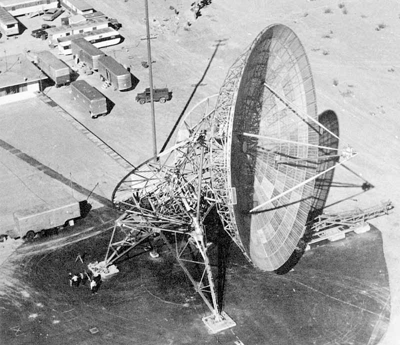
The original Pioneer Station as it appeared in 1958
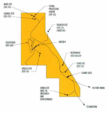
Today, through NASA leasing arrangements with the U.S. Army, the Goldstone Deep Space Communications Complex occupies 132 square kilometers (52 square miles) at the Fort Irwin military reservation. There are four operational deep spare stations: Echo (DSS 12), Mars (DSS 14), Uranus (DSS 15), and Apollo (DSS 16). A fifth station, Venus (DSS 13), is reserved for Network research and development. The stations are named for the first space mission or activity in which they participated; the station numbers indicate the sequence of addition to the Goldstone complex. Pioneer (DSS 11), the original Goldstone station, was deactivated in 1981. The Pioneer antenna has been designated a National Historic Landmark by the U.S. Department of the Interior.
The Goldstone complex is a self-sufficient working community with its own roads and airstrip, diesel-electric generators, and telephone system, and is equipped with all necessary domestic support services. The complex is accessible by paved highway from Barstow and by a scheduled JPL aircraft shuttle service from Burbank airport. The permanent buildings are constructed of cement block and concrete materials suitable to the California high desert environment. The Complex Support Department, which provides logistics, electronics repair, and the Goldstone administrative offices, is located in Barstow.
Goldstone is also the Network research and development center for advanced systems and prototype equipment that will extend the communication range increase the data rates, and improve station operations. The prototypes are thoroughly field-tested to meet Network standards for uniform performance reliable operation and economical maintenance.
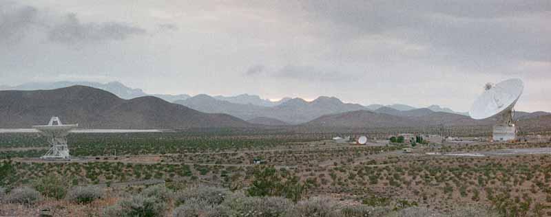
The surrounding hills and remote Mojave Desert location protect the extremely sensitive Goldstone receivers from Earth-based radio "noise" that would overwhelm ultraweak spacecraft signals
The main features at the Goldstone complex are the large parabolic dish antennas and their support structures. Although their diameters and mountings differ, all antennas employ a Cassegrainian feed system, which is essentially the some as the Cassegrainian telescope design used in optical astronomy. Each antenna dish surface is constructed of precision shaped perforated aluminum panels of specified surface accuracy that are secured to an open steel framework.
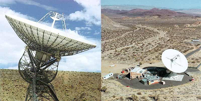
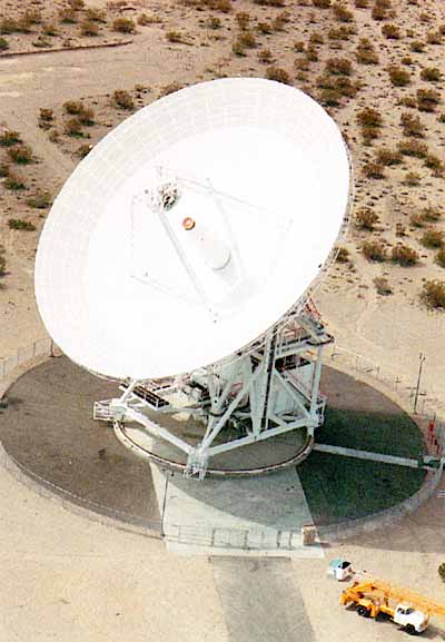
The Echo antenna (above left) has been extended in diameter from 26 to 34 meters to increase its sensitivity for outer planet missions. The Echo site is also the Goldstone administrative and support center. The Venus 26-meter antenna station is reserved for Network research and development and was in operation since 1962.
DSS 12-Echo
The Echo site has been in operation since 1960 and is named for its initial operation in support of Project Echo, an experiment that transmitted voice communications coast to coast by bouncing the signals off the surface of a passive balloon-type satellite. The original 26-meter antenna erected for the Echo experiment was moved in 1961 to the nearby Venus site.
The present Echo antenna, originally 26 meters in diameter, was erected in late 1961 and was extended to 34 meters in 1979. The antenna is patterned after radio-astronomy antennas then in use at the Carnegie Institute of Washington and the University of Michigan. The main features borrowed from the radio-astronomy antenna design are the mount and the celestial-coordinate pointing system. The axis of the polar or hour-angle gear wheel, which moves the antenna east and west, is parallel to the polar axis of the Earth and points precisely to Polaris, the North Star. The declination gear wheel, which moves the antenna north and south, is mounted on an axis that parallels the Earth's equator. A spacecraft in deep space appears in the sky much like any celestial object, rising in the east and setting in the west generally 7 to 14 hours later. The desirable feature of the polar-mount antenna is that (usually) once the declination angle has been set, only the hour-angle gear wheel is driven in order to track the spacecraft. The rate of movement, which counteracts the Earth's rotation rate, is approximately 0.004 degree per second.
The Echo antenna stands approximately 35 meters (113 feet) high and weighs approximately 270,000 kilograms (300 tons). The operating speed ranges from 0.25 degree per second down to 0.001 degree per second. The antenna can be operated automatically or manually and has a pointing accuracy of 0.020 degree in winds up to 70 kilometers (45 miles) per hour.
The Echo site is also the Goldstone administrative and support center. The low-profile buildings house offices, maintenance and repair shops, the communications center, the Goldstone transportation facilities, and a cafeteria.
DSS 13-Venus
The Venus site began operation in 1962 as the Network research and development station and is named for its first operational activity, a successful radar detection of the planet Venus. The 26-meter Venus antenna was originally located at the Echo site, where it was erected to support the Project Echo experiment described above. In 1961, the antenna was moved en masse by truck to its present location, a shielded site where research and development of high-power transmitters could be carried out without causing radio interference at the other stations, and where the electromagnetic radiation danger to personnel could be minimized by station layout.
Along with high-power transmitters, other capabilities developed and first tested at the Venus site include low-noise receivers, computer-controlled subsystems, digital signal processing, antenna arraying to increase telemetry data rates, remote station operations, and systems and equipment for NASA's Search for Extraterrestrial Intelligence.
Radar astronomy experiments, which employ high-power transmitters, low-noise receivers, precision timing systems, and digital signal processing techniques, have been used extensively to field-test and verify new capabilities before their introduction into the Network.
The 26-meter (85-foot) Venus antenna is equipped with an azimuth-elevation type of mount. Its hydraulic drive system is designed for relatively fast angular movement and can be operated at 2 degrees per second in elevation and azimuth. A new 34-meter antenna is scheduled to begin research and development activities in 1991.
The 9-meter (30-foot) diameter antenna located at the Venus site is no longer in use. It was used earlier for a number of research experiments, including master time synchronization transmissions to the overseas complexes. The time signals were directed to the other complexes by bouncing them off the Moon.
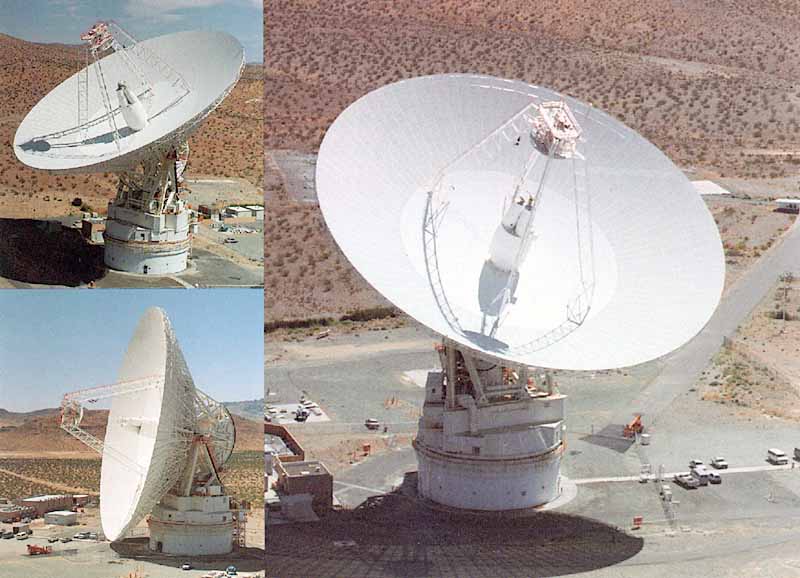
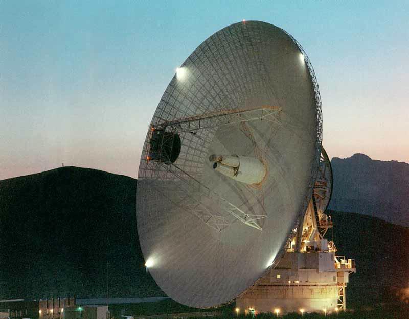
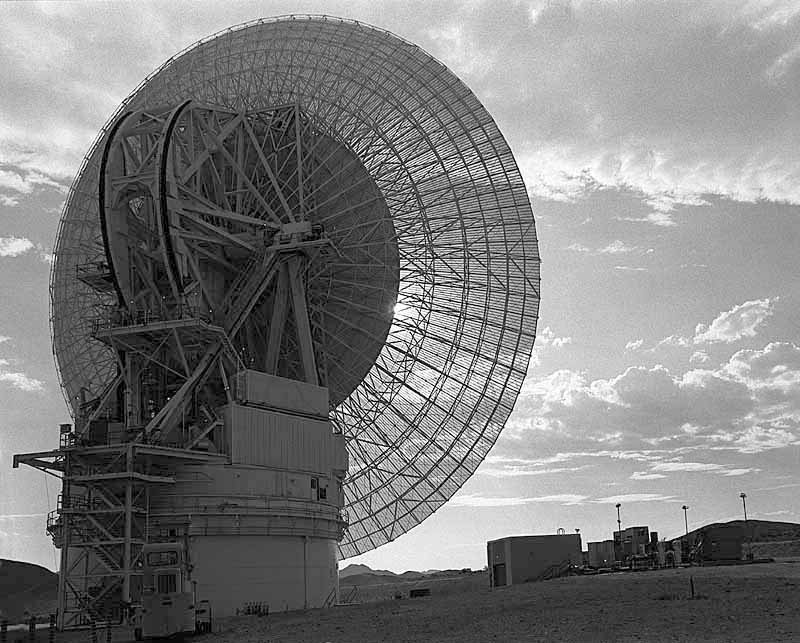
The Mars 70-meter antenna communicates with spacecraft at the edge of the solar system. This antenna is also used for radio and radar astronomy
DSS 14-Mars
The Mars station was completed in 1966 as a 64-meter (210-foot) diameter antenna, and begun tracking operations by easily acquiring signals from the 1964 Mariner Mars mission spacecraft across a distance of 328 million kilometers (205 million miles). The 64-meter antenna provided 6-1/2 times the transmitting power and receiving sensitivity of the original DSN 26-meter antennas and extended the range of the DSN 2-1/2 times. The Mars antenna was upgraded to 70 meters in June 1988. The improvement was in preparation for the 1989 Voyager 2 encounter with Neptune, at a distance of 4.5 billion kilometers (2.8 billion miles), and the spacecraft's eventual entry into interstellar space. The extension allows higher data rates to be received over longer distances, thereby increasing the scientific yield of all deep spate missions.
The overall height of the Mars station is 71 meters (234 feet); its total weight, including the concrete pedestal, is 7,262 metric tons (8,000 U.S. tons). The dish and its azimuth-elevation mounting structure on top of the pedestal weigh nearly 2.7 million kilograms (6 million pounds). The structure rotates in azimuth on three flat bearing surfaces that float on a pressurized film of oil about the thickness of a sheet of paper. The pedestal is over 10 meters (33 feet) high and contains 4.4 million kilograms (10 million pounds) of reinforced concrete.
The interior of the pedestal is partitioned into equipment rooms, operating and maintenance areas, and offices. The antenna-pointing control system is installed in a tower-like structure that rises through the (enter of the pedestal but is completely separated from it to provide a stable, vibration free platform. Because of the antenna's narrow receiving beamwidth, pointing accuracies of 0.006 degree are maintained to avoid losses in spacecraft signal power. Regardless of its position, the reflecting surface of the antenna must remain accurate to a fraction of the signal wavelength, meaning that the surface accuracy across the 3,850-square meter (4,600-square-yard) surface is within one centimeter (0.39 inch).
DSS 15-Uranus
The 34-meter-diameter Uranus station is the latest addition to the Goldstone complex. The station was completed in 1984 and used operationally for the first time in support of the January 1986 Voyager 2 flyby encounter with Uranus more than 3 billion kilometers (1.8 billion miles) away.
DSS 15 is equipped with an electrically driven azimuth-elevation type of mount. The antenna dish is supported by a steel spaceframe, which rotates in azimuth on four self aligning wheel assemblies that ride on a precisely leveled circular steel track. The track is held firmly in place by 16 tangent links that attach to a central reinforced concrete pedestal. The antenna dish structure is attached to the elevation gear wheel, which drives the antenna up and down. The operating speeds are 0.40 degree per second in azimuth and elevation.
DSS 15 is referred to as a high-efficiency antenna because the reflector surface has been precision-shaped for maximum signal-gathering capability.
Completed in 1984, the Uranus 34-meter antenna is the latest addition to the Goldstone complex.
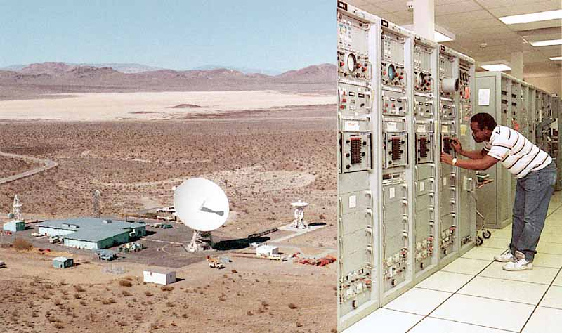
The Apollo 26-meter antenna station (above left) supports Earth-orbiting scientific, weather, and communications satellites. Located at the Mars site, the Goldstone Signal Processing Center (above right) remotely controls the 34- and 70-meter antenna stations and houses the electronics that recover the telemetry and navigation data from the spacecraft signal.
DSS 16-Apollo
The Apollo 26-meter antenna station was built in 1965 by the NASA Goddard Spaceflight Tracking and Data Network to support the manned Apollo missions to the Moon. The station and its Earth-orbiter tracking responsibilities were transferred to the Deep Space Network in 1985. The antenna has an X-Y axis mount and uses an X-Y coordinate system. The X-axis gear wheel drives the antenna north and south. The Y-axis gear wheel is mounted above the X-axis and drives the antenna east and west. The X-Y design allows the antenna to point on the horizon to pick up Earth orbiters just as they rise into view. The antenna operates at speeds up to 3 degrees per second in both axes in order to follow the fast-moving satellites, most of which are in orbits between 160 and 1,000 kilometers (100 and 630 miles) above the Earth.
DSS 16's operation schedule often includes receiving telemetry from as many as 15 different Satellites per day in both high and low Earth orbits. On occasion the station is assigned to support the launch phase of some satellites. A 9-meter (30-foot) antenna at the Apollo site is available for backup support.
The Signal Processing Center
The Goldstone Signal Processing center is the result of a 5-year upgrade program completed in 1985 to provide centralized remote control and performance monitoring of the 34- and 70-meter antenna stations (DSS 12, 15, and 14). The Apollo 26-meter station has not yet been equipped for remote operation. The center is located at the Mars site and contains the various subsystems that point and control the antennas, receive and process telemetry, generate and transmit commands, and produce the spacecraft navigation data. Formerly, these subsystems were duplicated at each of the stations. The centralized location allows a six-person crew to operate all three antennas as required by the day's tracking schedule. The center is connected to the antennas by fiber-optic links, by terrestrial microwave, and by coaxial and electrical cables.
The various flight project control centers, located in the United States, Europe, and Asia, are connected directly to Goldstone via the Ground Communications Facility at JPL. Command data are sent from the project control center to the Goldstone center, where the command message is generated, verified, and transmitted to the spacecraft. The telemetry received from the spacecraft is initially decoded at Goldstone, formatted for ground transmission, and delivered to the project control center in unprocessed "raw" form.
THE CHALLENGES AHEAD
Goldstone is a major contributor to the state-of-the-art technology that makes deep space communications possible. Network improvements in low-noise receivers, antennas, and signal processing systems which are developed and initially tested at Goldstone, have enriched the scientific yield from all spacecraft missions and extended the current communications link to the edge of the solar system. Exciting new challenges lie just ahead. It is now possible for Pioneer and Voyager spacecraft which were launched in the 1970s on missions to explore the outer planets, to continue their unique productive lifetimes as they leave the orbits of Neptune and Pluto, pass through the heliosphere, and enter true interstellar space. Their science objectives now become the astrophysics of the interstellar medium and our galaxy. Network engineers expect to extend and maintain the communications link with these spacecraft until their nuclear power supplies run out of fuel and their missions come to an end somewhere among the stars.
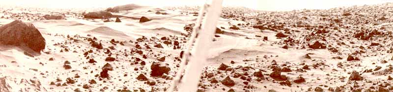
A panoramic view of the surface of Mars was photographed by Viking Lander 1 in 1976. The world science community anxiously waited as the first photographs were processed at JPL. Part of the Lander's meteorology boom, which supports a miniature weather station, is visible in the center of this picture.
National Aeronautics and
Space Administration
Jet Propulsion Laboratory
California Institute of Technology
Pasadena, California
JPL 400-326 May 1989
Back to the main Goldstone Apollo page.