The
Goldstone “Wing” Station
by Bill Wood
|
| The Goldstone ‘Wing’ station, DSS-11. Photo: Bill Wood. |
At Goldstone the DSS-11 Pioneer station was chosen to install the Apollo Wing USB system.
The Pioneer station was located about three miles north of the Apollo Prime station in a bowl shaped area surrounded by hills to reduce the effect of man-made RF noise on the Deep Space missions the station tracked.
In the photograph above the DSS-11 operations building has two wings.
The DSN Wing is on this side and slightly canted towards the antenna.
The MSFN wing is on the far side and is also canted towards the 26-meter Hour-Angle/declination antenna. The hydraulic pumps to move the antenna are located in the building just to the right of the antenna base.
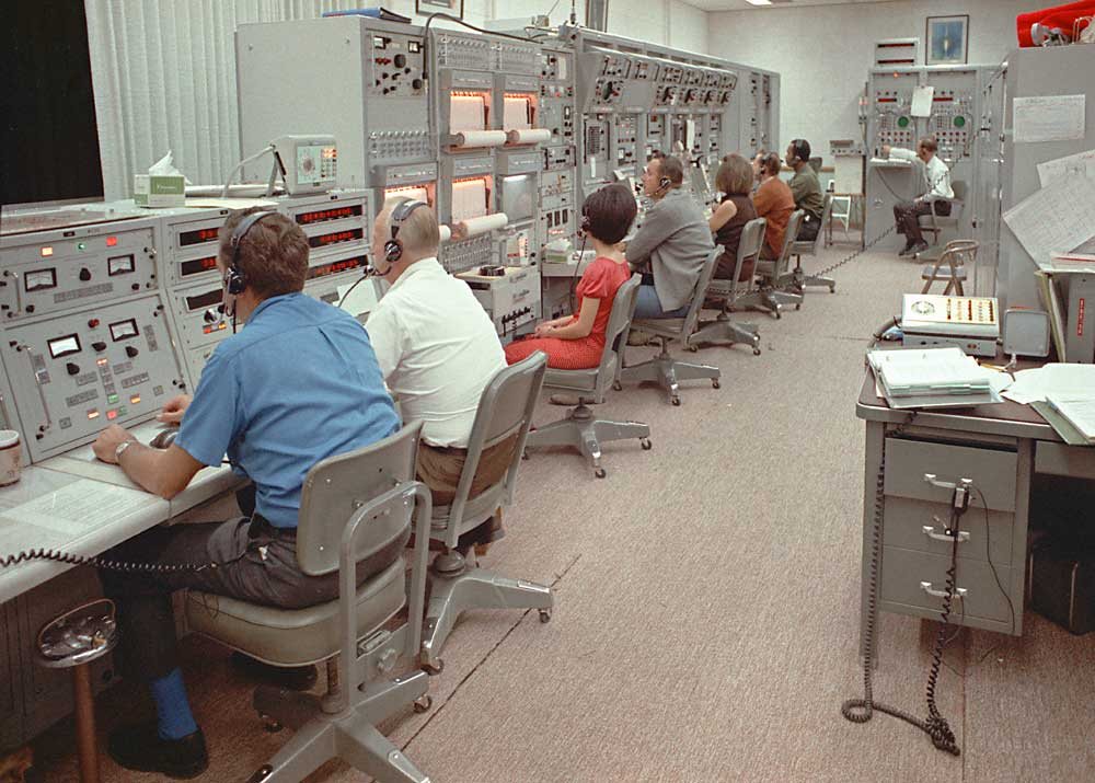 |
Goldstone ‘wing’ station consoles during Apollo 12. Photo: Bill Wood. |
This photograph, taken during the support of the
Apollo 12 mission, shows the Antenna Servo console and APP/TDP
control, the USB System Monitor racks, the RF test equipment
and subcarrier modulator rack and the two Receiver-Exciter systems.
As at the prime station the Mark 1 Ranging systems are at the end of
the room. The APP/TDP racks are on the right side of the photo. The USB Timing
System is outside the right edge of this photo.
People in this photo, from left to right are Al
Norman, Antenna/Servo, John Passwaters, APP/TDP, the unidentified
young lady is the Systems Monitor operator. Next is Tom Jonas, RE Engineer,
running the main exciter, Norma Wilson, RE operator, another unidentified
RE operator, Chuck Finley, RE technician, and finally on the MK-1 ranging
system is Dick Moser, Ranging/Timing technician.
The equipment in the MSFN Wing was nearly identical to the Unified S-band equipment
at the Prime station. The only thing missing was the Signal Data Demodulator
racks. And these were connected to the Wing station by a dedicated microwave
link between the two stations.
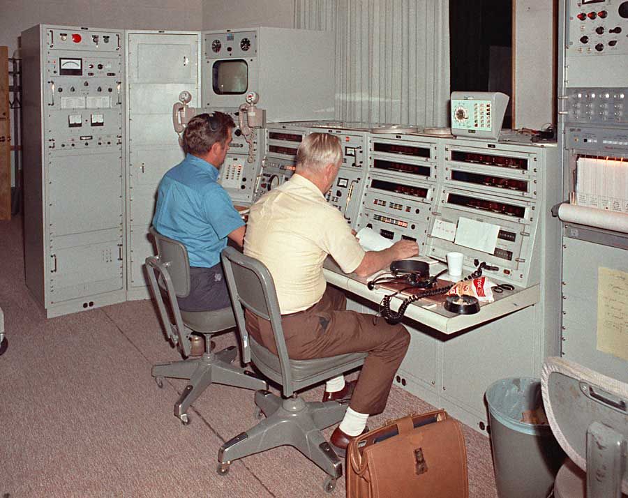
Control of the antenna mounted equipment was switched between the DSN and MSFN Wings through the use of a complex switching system that was tightly controlled as to when and if a switch were made. Once the switch is made to the MSFN side, the entire antenna was under the direct control of the operators shown here.
 |
| Antenna control console. Photo: Bill Wood. |
This photo shows the full antenna control console at the Wing station. The system was provided by Collins Radio as part
of the MSFN system.
All of the electronics were designed to work with the DSN antenna, to the extent of using hour-angle/declination angle encoders and the use of the DSN constant pressure hydraulics system. The 26-meter XY antenna used variable pressure hydraulics. As at the Prime station equipment failures were very rare. The S-band masers were the major maintenance item.
 |
| Looking east. Photo: Bill Wood. |
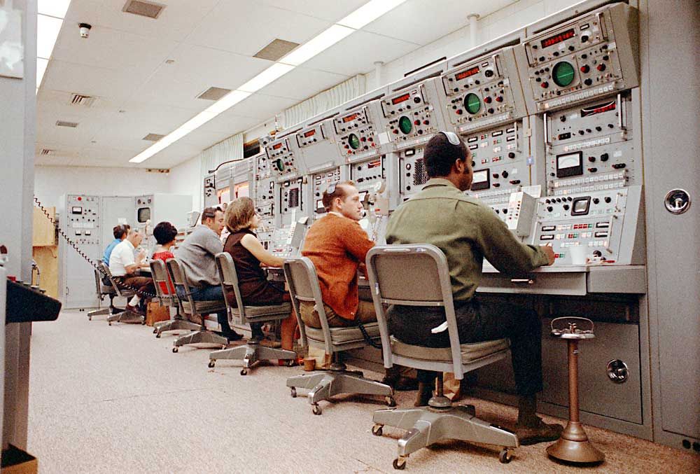
Here is a view looking east from the other end of
the room.
On the right side of this photo is the keyboard of the Model 28 teletype machine that monitored the Tracking Data Processor low speed output that was sent to GSFC for use in the real-time computing system.
As a side note, the Wing control room had a carpeted floor that, when coupled with the acoustic panelled walls, made for very quiet operation.
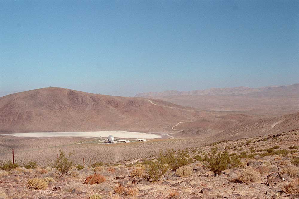 |
| Looking east. Photo: Bill Wood. |
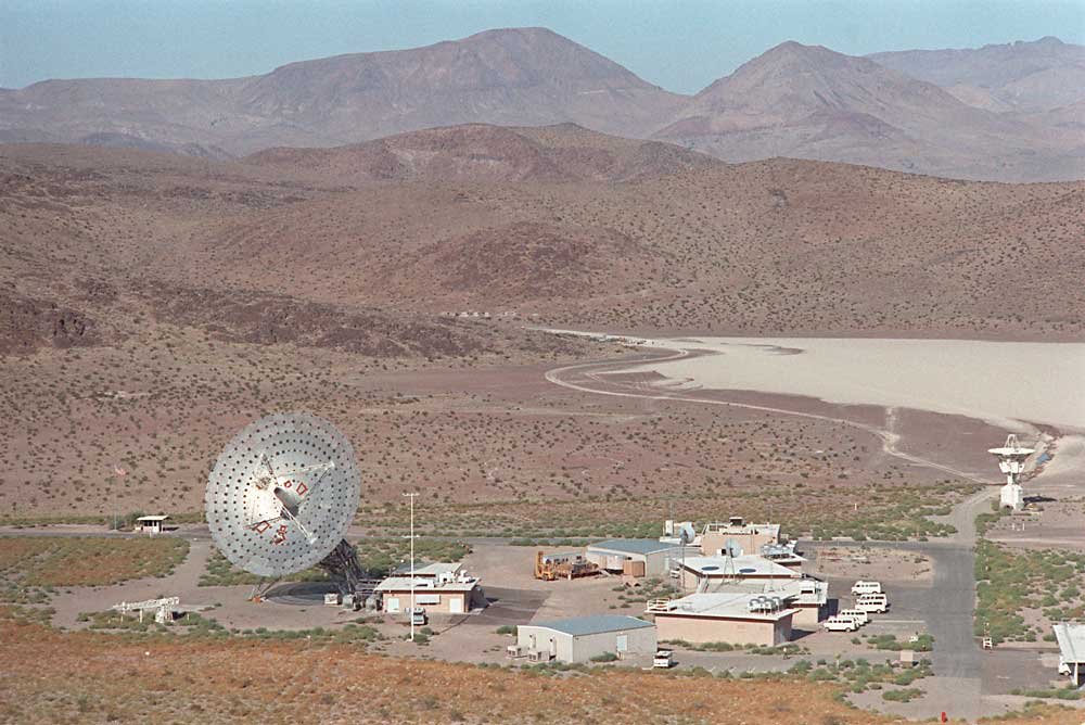
This photograph shows the isolated location of the Pioneer station.
On the far side of this photo, taken from the DSS-11 collimation tower, is the ridge that separates DSS-11 from the nearby DSS-14 Mars antenna. You can see the passive microwave repeaters on the top of this ridge.
The unpaved road that goes from the station up the ridge is the access road to the microwave repeaters. It took a four wheel truck, and occasionally a bulldozer, to make it up the hill. Luckily the repeaters were passive!