by Bryan Sullivan
Written
January 2013, updated May 2014.
PART A.) STATION OPERATIONS AREAS |
MAJOR SECTIONS
Operations were divided into clearly defined areas within the Honeysuckle Creek (HSK) Tracking station. The major sections were –
- Unified S-Band (USB) Section
- Data [Processing] Section
- Communications Section
- Station Operations Section
- Station Simulation System
- Technical Support Section
- Facilities Section
- Logistics Section
- Administration Section
- Canteen
1.) UNIFIED S-BAND (USB) SECTION
The USB system included the major subsystems of the Antenna and its hydraulic Servo Control equipment, special purpose antenna Tracking and Positioning processors, the cryogenically cooled Parametric Amplifiers (PARAMPS), four sensitive S-Band Signal Receivers and two High-Power Amplifier (PA) transmitters, the PM and FM Signal Data Demodulators (SDDS), two special purpose computers for the Ranging Systems and the station’s Time Standard equipment.
THE ANTENNA
The precise geographical antenna position was eventually determined to a very high degree of accuracy using Very Long Based Interferometer (VLBI) techniques.
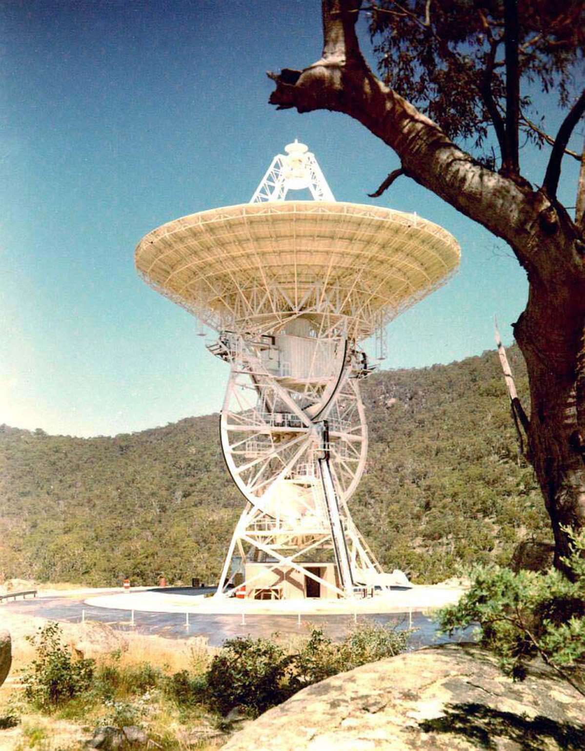
The 26 metre diameter antenna configuration was an XY mount, which meant the antenna tilted in two directions, north to south, and east to west. The XY mount allowed the antenna to track fast moving spacecraft smoothly over the antenna’s zenith.
|
The 26 metre antenna. Photo via John Saxon. |
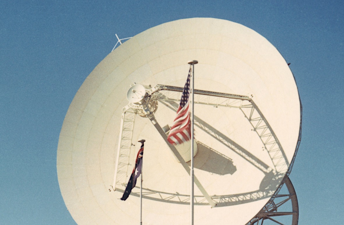
A small 2 metre dish located at the apex of the quad legs was an Acquisition Aid Antenna. With a wide three degree beam width it rapidly aided signal acquisition by the main dish. It was particularly useful for the earth orbit phases of the Apollo missions.
|
The Acquisition Aid at the apex of the quadrapod.
Large, Larger. Photo: Hamish Lindsay. |
Directly behind the antenna dish was a room containing the transmitters (PA’s), and the cryogenically cooled parametric amplifiers (PARAMPS).
Hydraulic servo motors at the base of each axis gear controlled the XY angular movement of the dish.
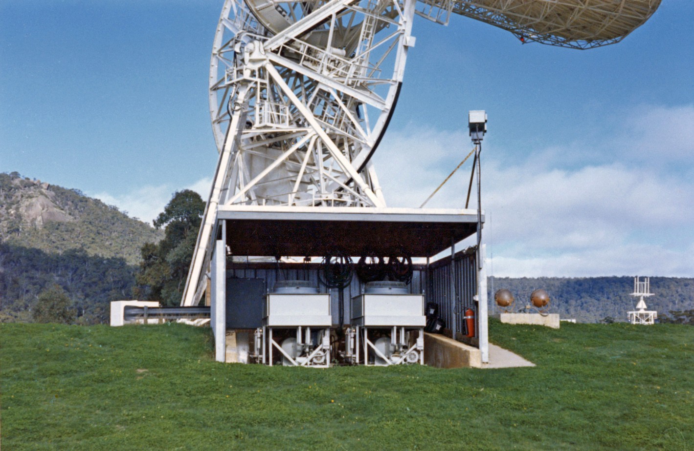
High-flow coolant heat exchangers for each of the Power Amplifiers (PA’s or transmitters) was housed in a separate shed adjacent to the concrete antenna pad. The large heavy PA power supplies and motor generators were housed in a room at ground level directly under the antenna structure.
|
The heat exchangers in the shed next to the antenna pad.
Photo via Milton Turner. |
The 26 metre antenna had the following specifications:
Beam width: 0.43° ± 0.05°.
Pointing accuracy: 40 seconds of arc.
Maximum tracking rate: 3 degrees per second.
Polarization: Right or Left Hand Circular, remotely switchable.
Gain: 51db up, 53db down.
Acceleration: 5° per second (slew rate).
RADIATION HAZARDS
Personnel were not permitted to be up on or near the base of the antenna (referred to as ‘the pad’) at times when either transmitter was radiating. High powered S Band (2.1 – 2.2 GHz) frequencies constituted a considerable radiation hazard.
Antenna safety features included bright flashing red lights around the perimeter of the dish as well as a very loud pulsating klaxon horn which was heard several kilometers away.
The collimation tower located on the western ridge, about three kilometers away, also presented a radiation hazard to personnel if they were on the tower conducting calibrations or testing during an accidental ‘turning on’ of the transmitters.
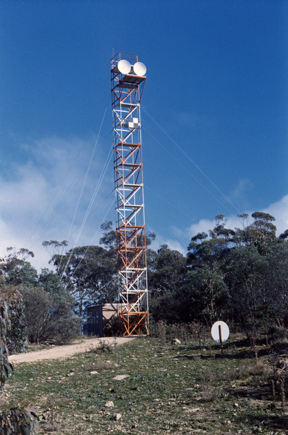
The collimation tower referred to as ‘the coll tower’, supported two small antennas (dishes) along with special test equipment to simulate a spacecraft. With the main tracking antenna pointed at the coll tower a comprehensive test of all the USB equipment and functions could be performed. Problems occurring during a tracking period could be quickly resolved as being with either the spacecraft or with the station equipment.
|
The Collimation Tower.
Large, Larger. Photo via Milton Turner. |
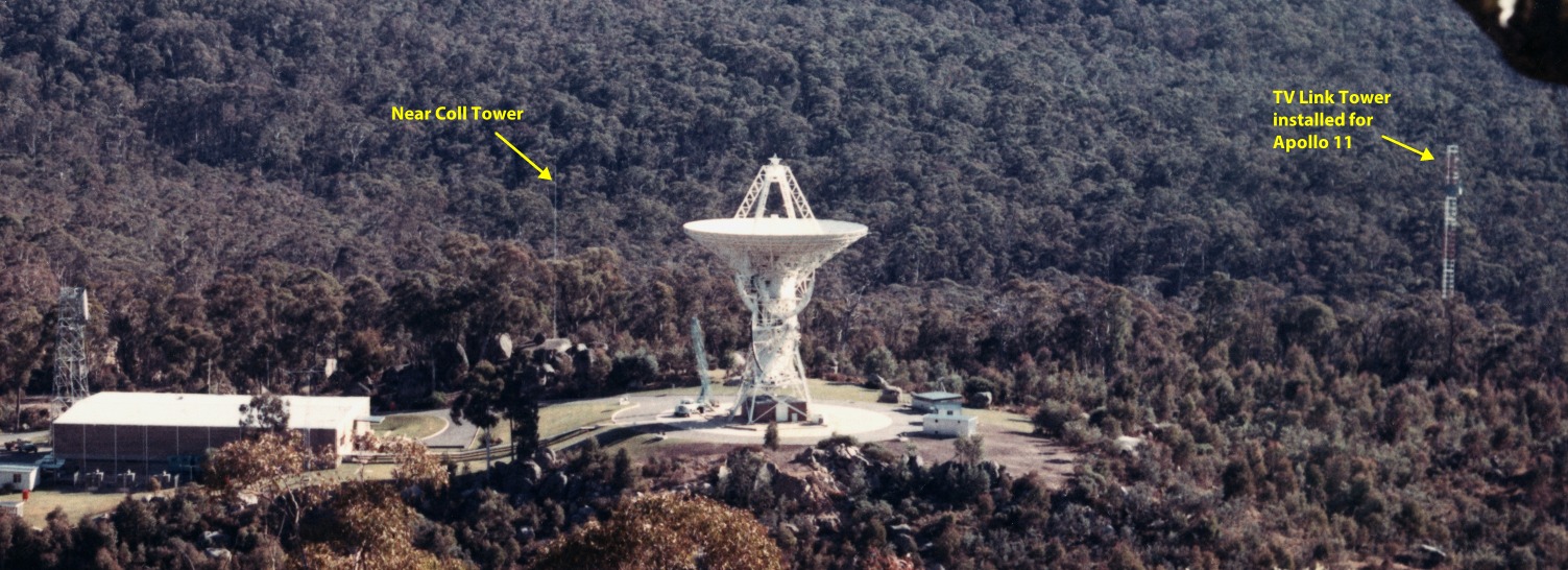
A small ‘near’ collimation tower was located among the gum trees just behind the station’s upper car park. It consisted of a wind-up tower with a small locally made S-band antenna. This provided very low power S-band signals from the Station Simulation System to the 26 metre tracking antenna.
|
The small ‘Near Coll Tower’ was mounted on the ground behind boulders, around 90 metres WNW of the main antenna.
Neil Sandford recalls: “It was a Hills crank up of 3 twenty-foot sections with a 50 mm pipe extension to mount the small antenna.”
At the far right is the temporary TV relay tower erected for Apollo 11 TV.
Large, Larger (800kb). Full photo here.
Preserved and scanned by Neil Sandford, restoration Colin Mackellar. |
In the early days, prior to the establishment of an air traffic exclusion zone of eight kilometers around the station, the air traffic control tower at the Canberra airport had to be informed before any station transmissions commenced.
Spurious radio frequency interference (RFI) was a potential problem for the sensitive receiver subsystems particularly at times of critical mission events. Careful checks were made for spurious RF noise sources such as signal generators used either for simulation exercises or in the electronics workshop, even down to the gardener’s ride-on lawn mower. At such times motor vehicle movements around the station were restricted, as was any on-coming shift staff cars, by a flashing red traffic light several kilometres down the station access road.
All light fittings used throughout the station were fitted with incandescent bulbs as fluorescent lights could have been a source of interference.
USB SUBSYSTEMS
GENERAL
The USB subsystems included the servo control console and two special purpose tracking and positioning processors to control the antenna, the signal receiver and transmitter control consoles, the subcarrier data demodulators, the station timing standard, the ranging subsystem and the paper chart monitoring recorders.
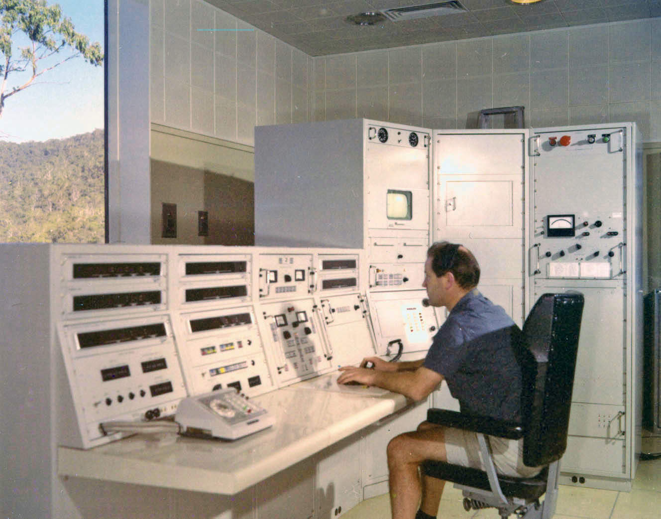
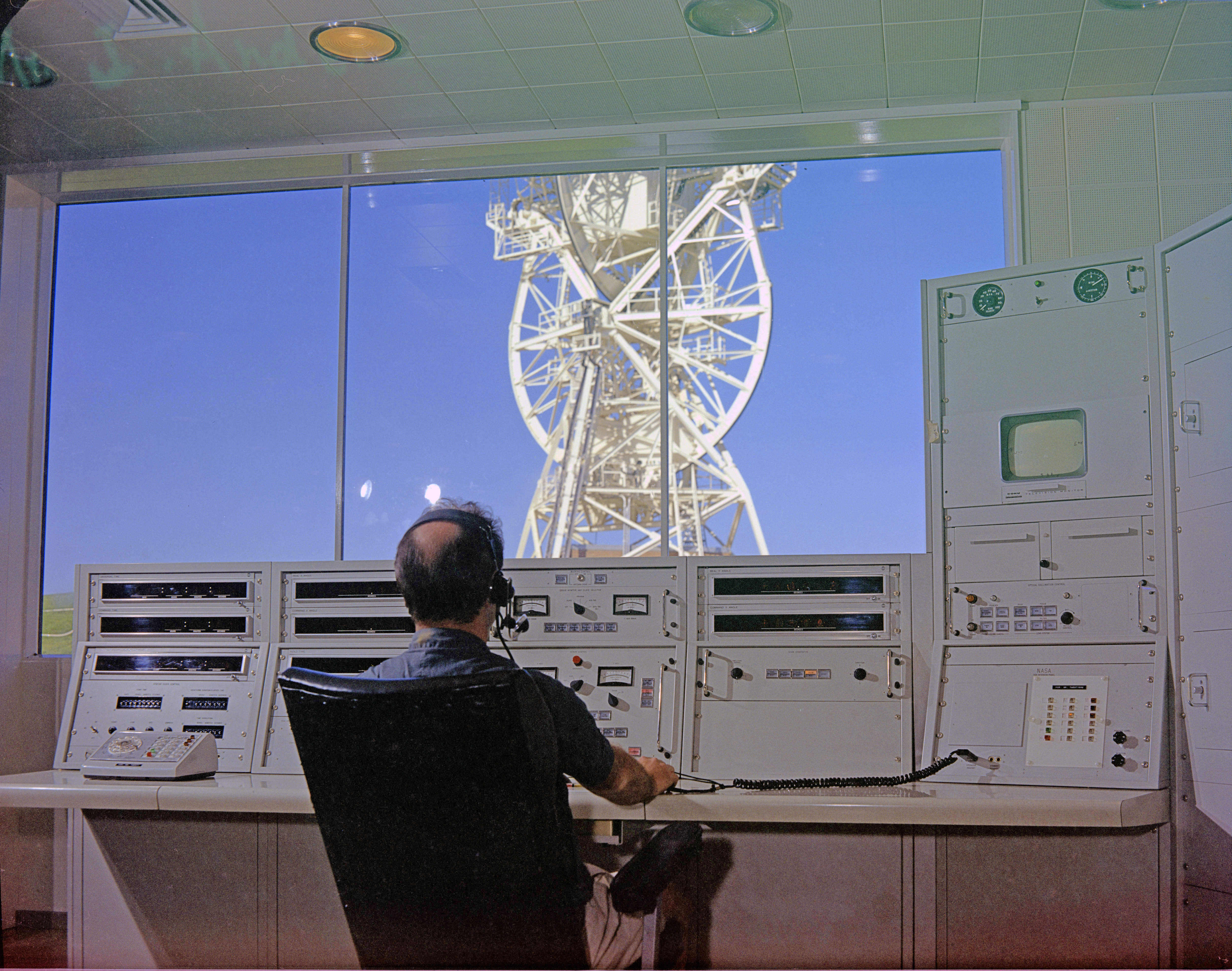
The servo control console faced the only window in the operations area, to enable the servo operator to observe the movement of the antenna.
|
Ian Anderson at the Servo console.
Photo Hamish Lindsay, via John Saxon. |
|
Ian Anderson at the Servo console, looking through the window to the antenna.
Photo Hamish Lindsay, 5x4" negative scan by Colin Mackellar. |
|
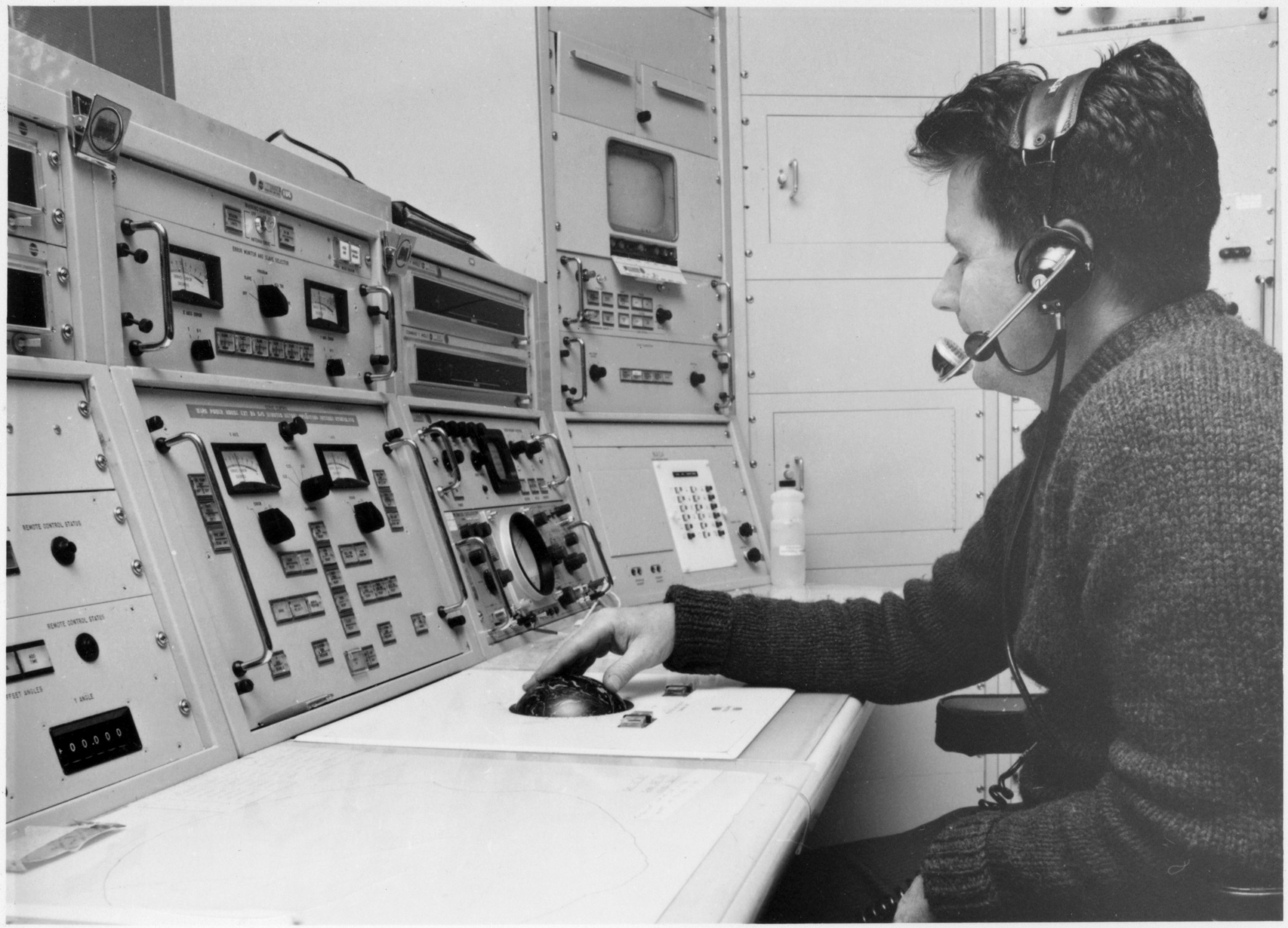
Paul Mullen moves the antenna with the track ball at the Servo console.
Photo: Australian News and Information Service.
Scan: Colin Mackellar. From Tom Reid’s album. |
RECEIVERS
The S-band signals from the parametric amplifiers were passed to the receivers located in the USB area. Associated with the receivers were several subsystems performing functional processes of doppler extraction to produce a range-rate signal, two-way communications with the spacecraft using a phase-lock loop technique, and angular tracking for the antenna control and servo drive equipment. The receivers also operated in conjunction with the digital ranging subsystem to provide a continuous range between the spacecraft and the tracking station.
Two intermediate frequency subcarrier signal outputs, a phase modulated (PM) and a frequency modulated (FM) from the receivers were passed to the Subcarrier Data Demodulator System (SDDS).
|
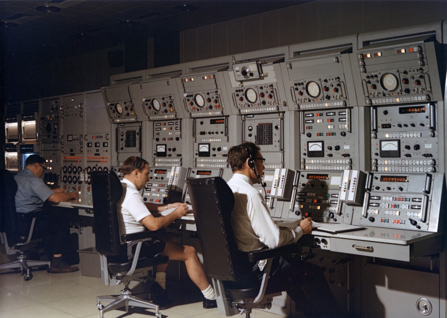
At the Power Amp control panels (far left) is Bruce Cameron, and at the Receivers, Len Litherland and Eric Gadd.
Large, Larger.
Photo: Hamish Lindsay. From Tom Reid’s album, with thanks to John Saxon.
Scan: Colin Mackellar. |
POWER AMPLIFIERS
The Power Amplifiers (transmitters) used klystrons which delivered a continuously variable output from 1 to 20 kilowatts. The bandwidth of 10 MHz was wide enough to accommodate both spacecraft uplink frequencies. A drive current 500 milliwatts produced the full 20 kilowatts output power from the antenna.
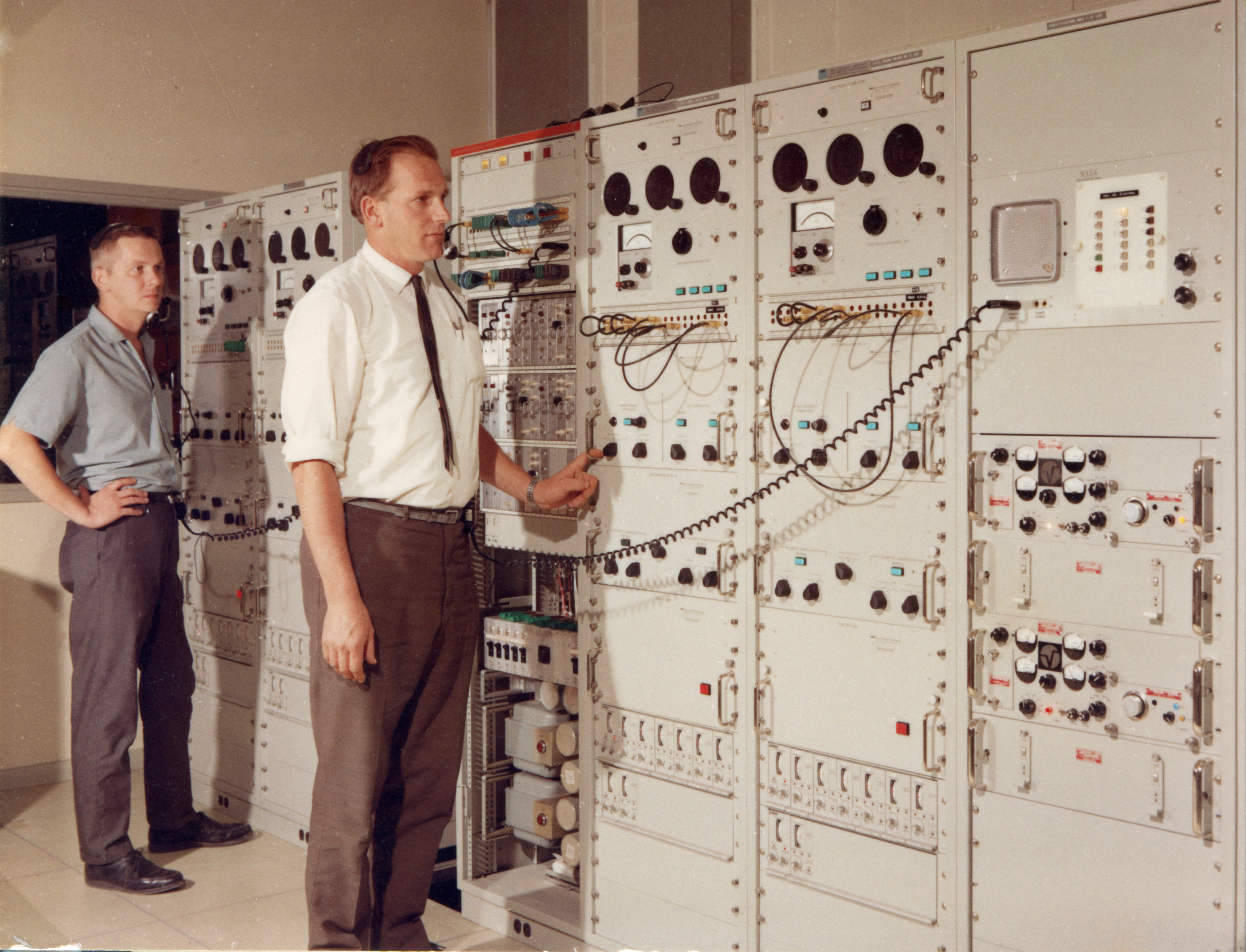
|
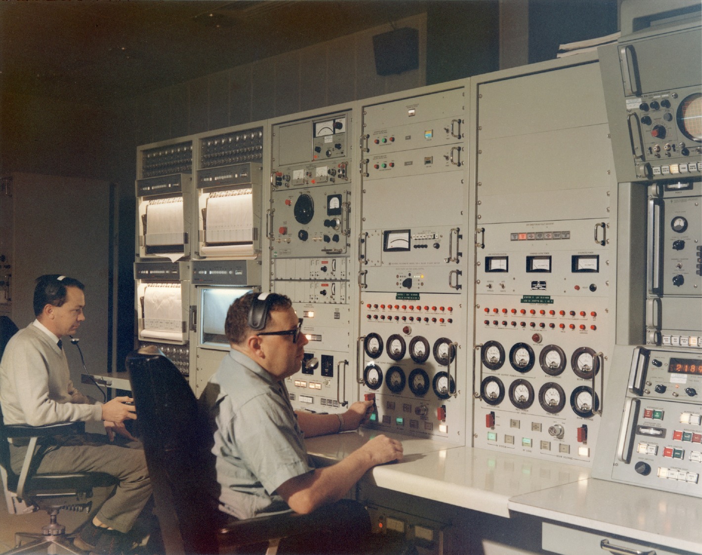
Mike Evenett at the USB System Monitor (left) and Bruce Cameron at the controls of the two 20 kW S-band Power Amplifiers.
Large, Larger, Largest.
Photo: Hamish Lindsay.
From Tom Reid’s album. Scan: Colin Mackellar. |
SUBCARRIER DEMODULATION
The Subcarrier Data Demodulator System (SDDS) demodulated signals from the S-band (USB) receiver systems of Honeysuckle Creek and Tidbinbilla stations and from the Parkes Radio Telescope. These composite signals contained the voice, telemetry, ranging, biomedical, television and scientific data subcarriers.
The SDDS equipment (usually referred to as 'suds'), demodulated the individual PM (phase modulated) and FM (frequency modulated) subcarriers which were further modulated with pulse code modulation (PCM) and pulse amplitude modulation (PAM) telemetry bit streams, as well as the voice and biomedical data.
As Apollo missions progressed the complexity of downlink subcarrier signals processing increased dramatically. From Apollo 7 with three astronauts in one Command Module (CM) to Apollo 15 with two spacecraft supporting one astronaut in the CM and two astromauts in the Lunar Module (LM).
During the lunar surface operations of the Apollo 15,16 and 17 missions a lunar rover vehicle (LRV) transported two astronauts across the lunar surface while the orbiting CM astronaut simultaneously conducted scientific experiments and launched a sub-satellite into a lunar orbit. The LRV and the sub satellite each provided a third and fourth downlink (S-band) carrier signal. This further complicated the ground tracking operations and signal path selections. These downlinks required continuous tracking in real time by the Manned Space Flight Network (MSFN) stations.
The CM spacecraft was capable of recording the on-board realtime data while it was out of MSFN tracking coverage, eg in earth orbit or behind the moon. The on-board recorder was operated by real time command from Mission Control. Both playback data and real time data was downlinked simultaneously on separate subcarriers.
It can be seen from the above that ground signal processing requirements for each tracking station became more complicated as the APOLLO missions became more technically demanding.
The S-Band downlinks supported a variety of signal combinations including:
1. astronaut voice primary, backup and emergency (morse) key.
2. real time and playback telemetry, both high and low bit rate.
3. ranging codes and a television signal.
4. scientific data in real time or playback.
5. hardline biomed data.
6. astronauts life support backpack telemetry.
7. lunar rover telemetry.
The above signal combinations varied depending on a particular mission phase or event in the overall flight plan and were referred to as the downlink modes. Each tracking station received a site configuration message (SCM) about one hour prior to the start of its tracking period. The SCM defined the physical systems configuration and signal flow paths required to support the up-coming tracking operations.
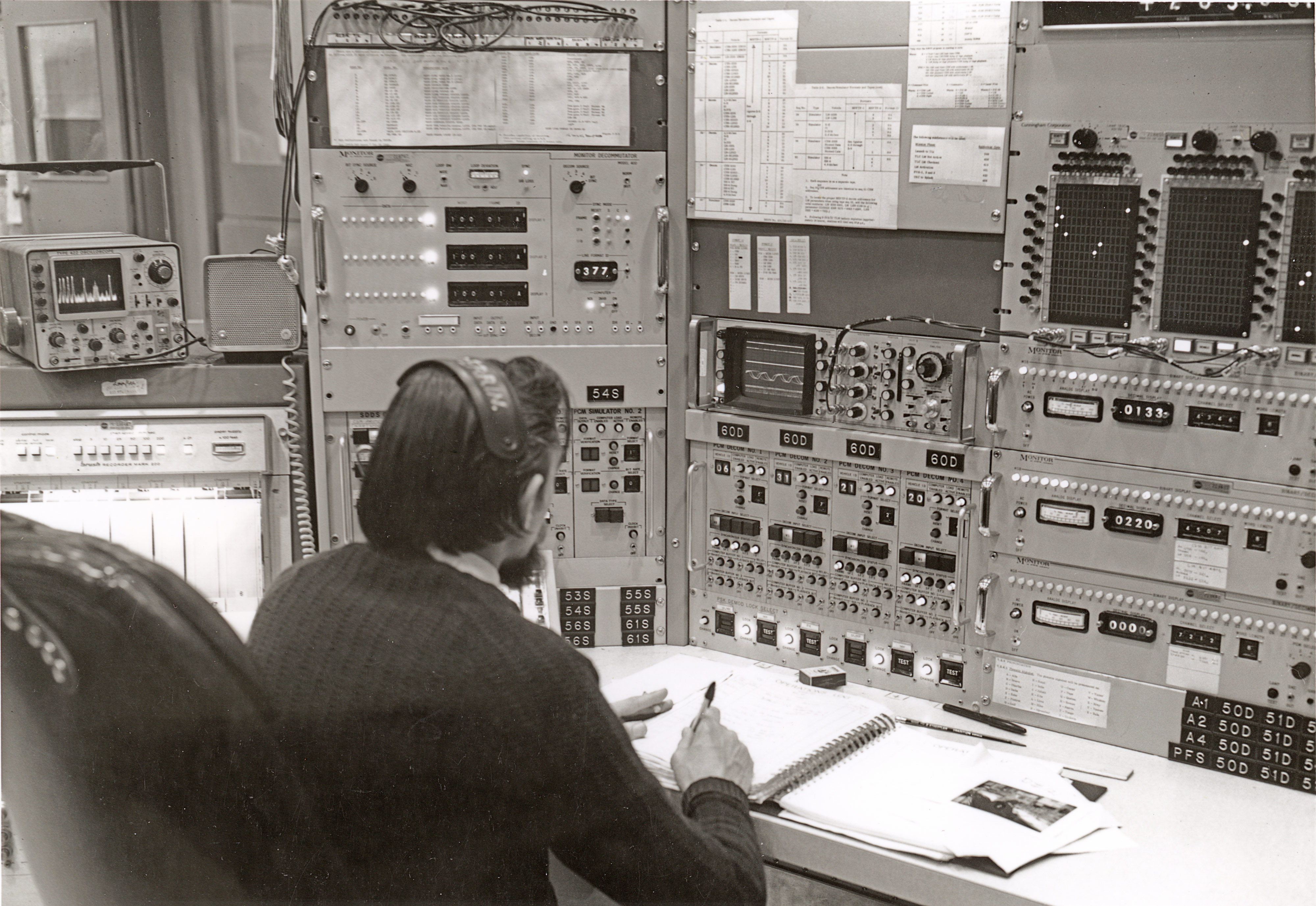
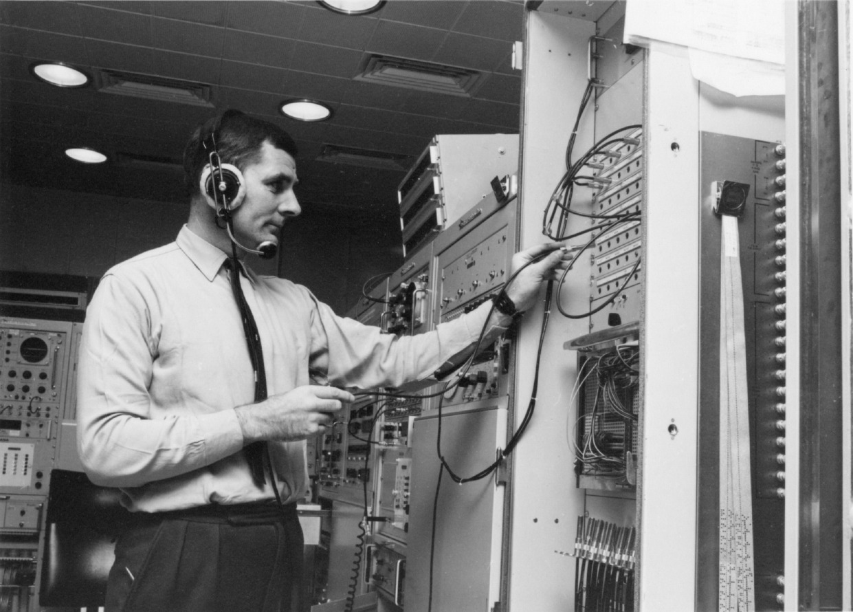
Signal flow paths were established using a somewhat untidy arrangement of patch cords and jack fields as illustrated in this photo of Jim Hanlon in the Telemetry area, at the patch panel of one of the Decoms –
For the later Apollo missions some of the untidy patch cords were replaced with matrix switching panels as shown in the top right of this photo –
|
Bill Perrin at the telemetry monitoring console during Apollo 15.
Photo: Hamish Lindsay. Scan: Colin Mackellar.
|
The television signal was demodulated from the FM subcarrier and passed to the station’s television processing equipment.
|
John Mitchell (foreground) and Rich Mirdas at Data Demods.
The window on the left is into the Simulation Room.
Photo HSK-5/9/7/2 - 21: Hamish Lindsay, 15 February 1967.
August 2022 scan: Craig Lindsay. 3.3MB. |
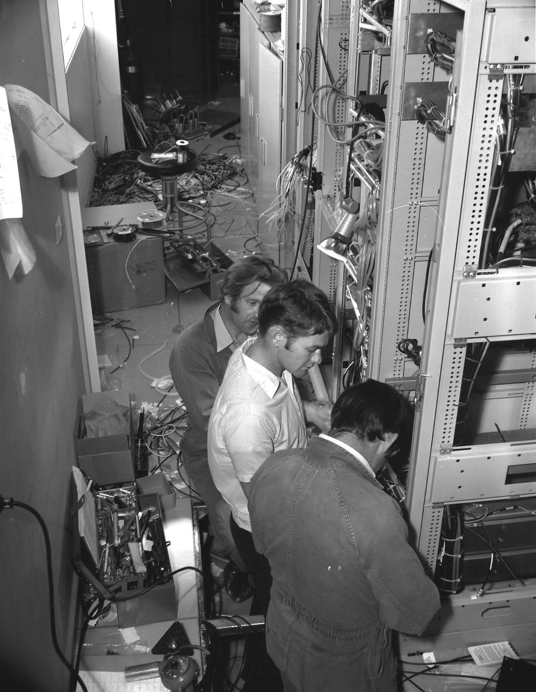
|
Jerry Bissicks, Kevin Gallegos and Graham Fraser are
terminating new cables behind the Data Demods (SDDS) for the upcoming
Apollo 15 mission. Photo: Hamish Lindsay.
|
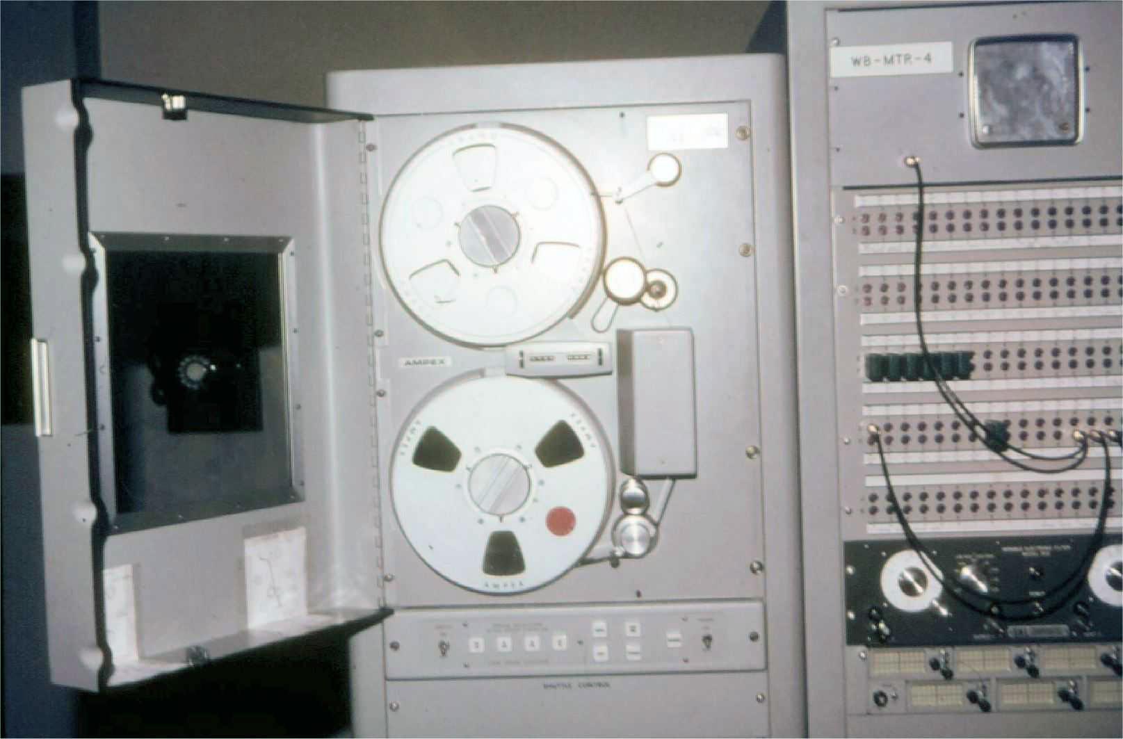
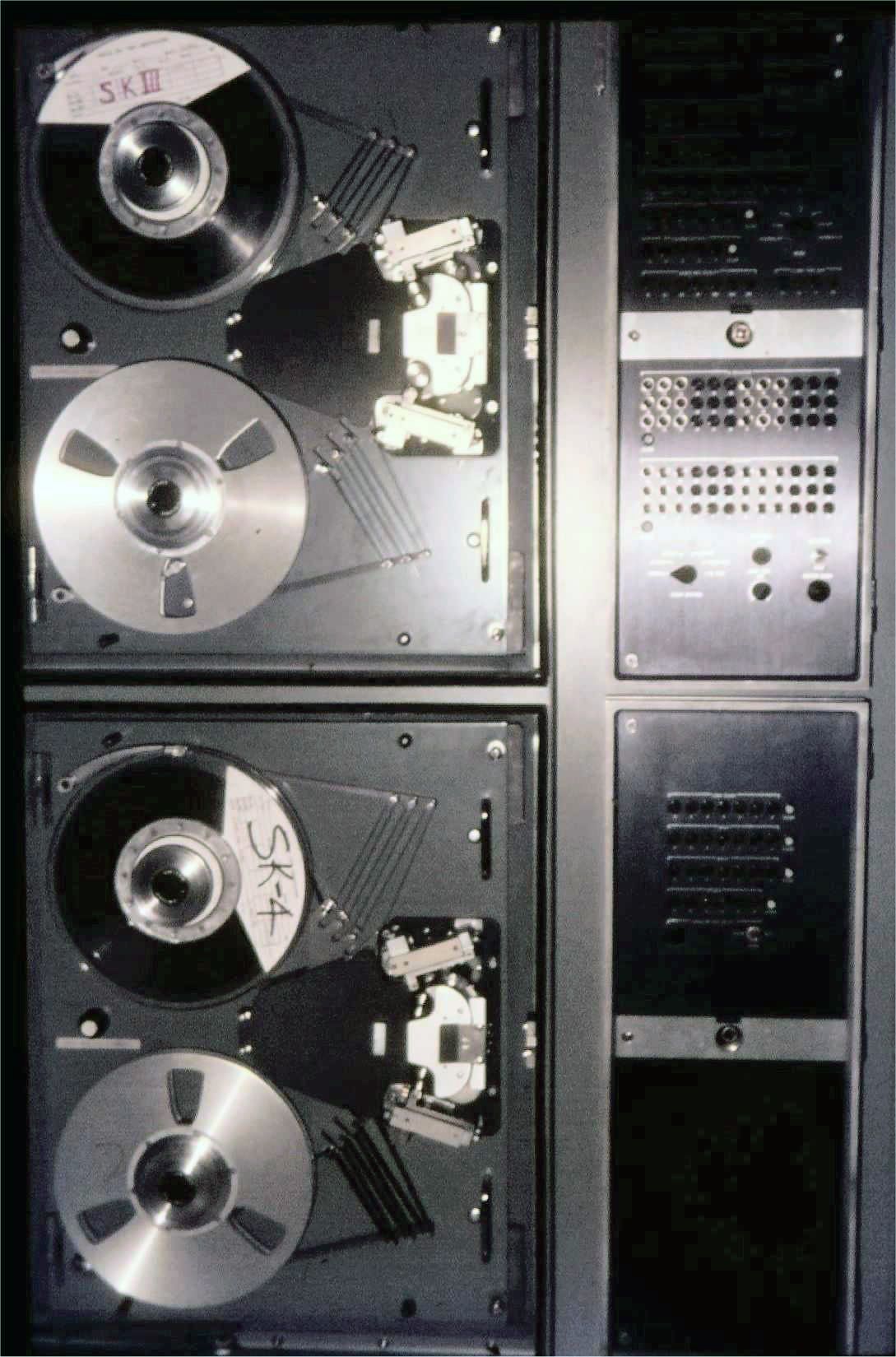
All demodulated voice signals were monitored by the HSK Communications Technician (COMTEC) who made selections based on the best signal source. The voice signals were recorded on analog reel-to-reel magnetic tape recorders well as being sent in real time to the Mission Control Centre (MCC) via NASCOM 1 undersea or satellite circuits.
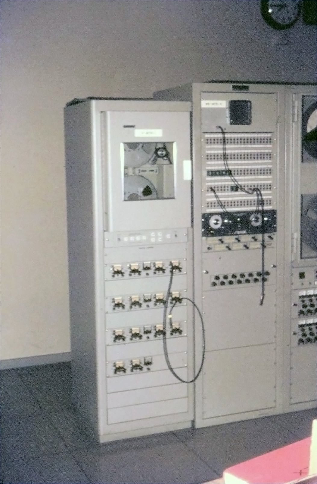
|
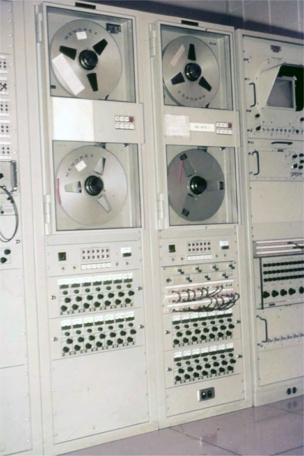
14 track voice recorder. Photo: Ian Hahn. |
|
14 track voice recorder, showing the tapes. Photo: Ian Hahn. |
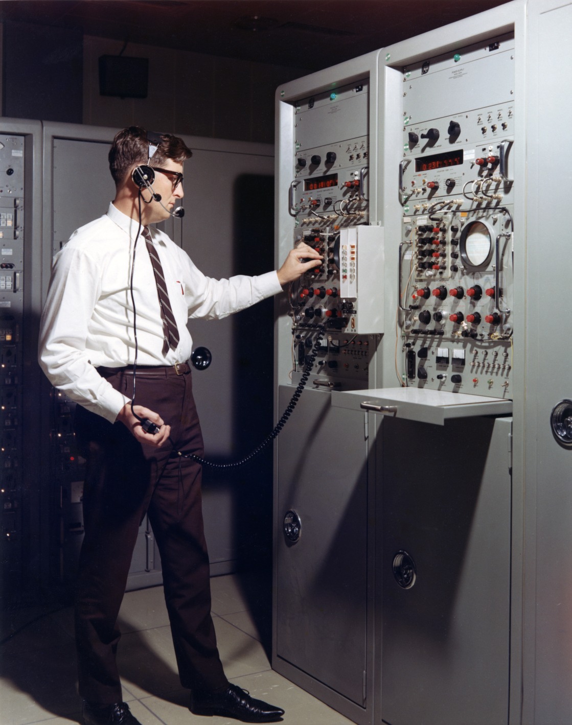
STATION TIME STANDARD
|
Clive Cross at the Frequency and Timing area.
Large, Larger, Largest.
Photo: Hamish Lindsay.
Scan: Colin Mackellar.
From Tom Reid’s album, with thanks to John Saxon. |
All the operations activities of the station mission support, interface and readiness testing revolved around time. The station had dual time standards located in the USB area. These provided multiple digital readouts, electronic pulses and various coded formats for time tagging all data produced on and/or leaving the station.
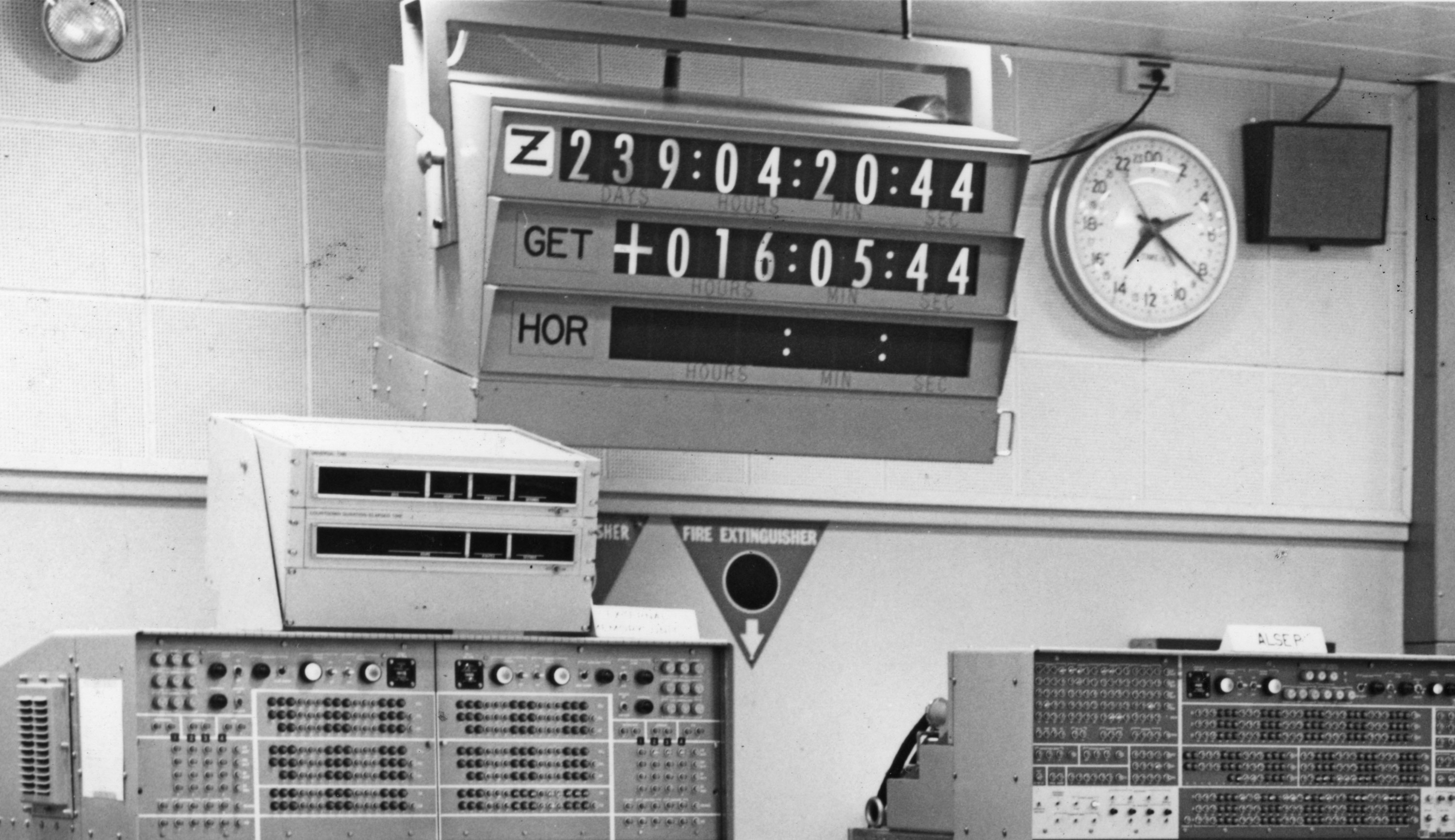
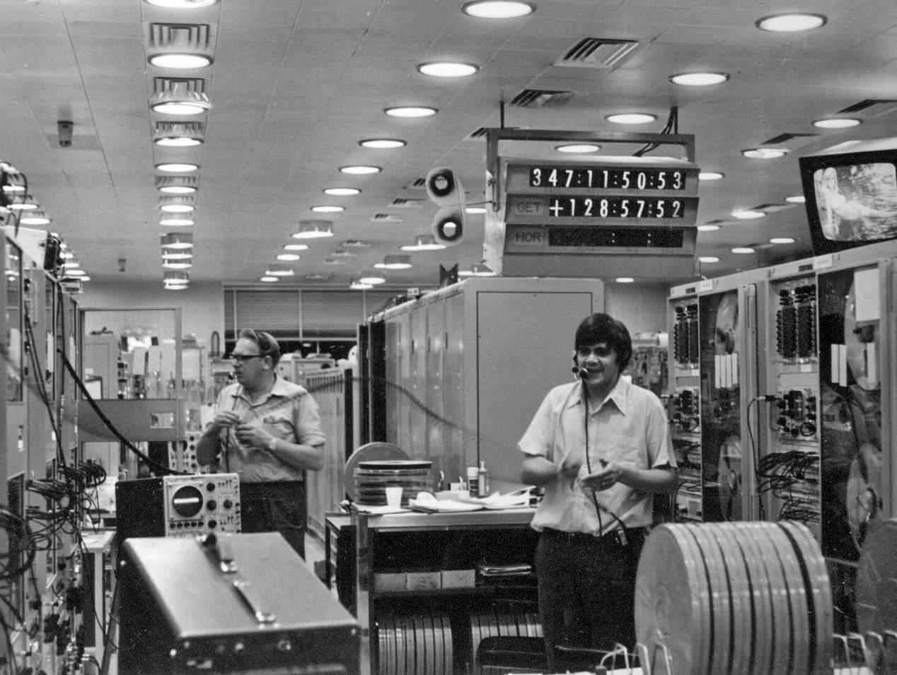
Three main forms of time were displayed around the operations areas:
Universal Time (UT) also known as Greenwich Mean Time (GMT) or Zulu (Z) time. Zulu time was used throughout the NASA tracking network by operations personnel as a common time reference. Time was displayed via digital readouts, as well as 24-hour analog dial clocks with two separate hour hands to show both zulu time and local time.
Ground Elapsed Time (GET) was also used by all operations personnel for both planning and as an event time reference. Each mission Flight Plan was written months ahead using a time that began from zero at lift off. The GET clock started as a minus count before the mission, ending with the familiar “three two one, we have lift off”. The moment the launch vehicle left the ground the GET clock would count through zero and begin counting up, and continue counting in hours, minutes and seconds until the end of the mission. All operations personnel knew exactly where events were in the flight plan from reference to the GET clock.
Horizon Time (HOR) was used only by the individual tracking stations to give a reference for events occurring on the stations prior to the start of their tracking period. The HOR time would count down from H minus 30 minutes prior to first acquisition of signal (AOS) from the spacecraft.
|
Time displays – in the Computer section.
From a photo by Hamish Lindsay. |
Accurate time keeping was essential for precision tracking, and various methods were used to keep the station time within ±10 microseconds of Universal Time (UT). Special radio stations transmitting in the HF short-wave bands known as WWV and WWVH were used for a coarse time check.
For a more vernier measurement down to ± 10 microseconds, the 100 kHz Loran C navigational signals were used. The North West Pacific Loran C chain was the nearest to Honeysuckle Creek, with delays calculated for the seven ‘hops’ from the Iwo Jima island master station.
The prime frequency source was a Hewlett Packard Cesium Beam Frequency Standard which provided a stability of around 1 in 10-10
seconds which controlled a Rubidium Frequency Standard. This combined the advantage of the stability of the Cesium unit with the low noise signal of the Rubidium unit.
RANGING
Ranging was a digital code transmitted to the spacecraft which returned it for time comparison with the original code. The pseudo random noise range code, generated by a dedicated ranging system, was a combination of digital pulse codes phase modulated onto the S-band uplink carrier.
The spacecraft turned the random pulse code around through the transponder and returned via the downlink signal. Complex processing by the station’s ranging subsystem determined the spacecraft’s range to an accuracy ± 1 metre
|
Bernard Smith at the twin Mark-1 Ranging equipment racks.
Large, Larger.
Photo HSK-5/9/7/2 - 20: Hamish Lindsay, 15 February 1967.
From Tom Reid’s album. Scan: Colin Mackellar. |
2.) DATA PROCESSING SECTION
2.1) TELEMETRY PROCESSING
The Data Section included the major subsystems for processing all of the telemetry data from both the Command Module (CM) and Lunar Module (LM) spacecrafts as well as the Lunar [Rover] Communications Relay Unit (LCRU). Special purpose processors handled both the Pulse Amplitude Modulation (PAM) and Pulse Code Modulation (PCM) data streams received from the Signal Data Demodulation Subsystem (SDDS).
|
Rex Jones (seated) and Eric Stallard in an early view of the Telemetry section.
Photo: Hamish Lindsay via John Saxon.
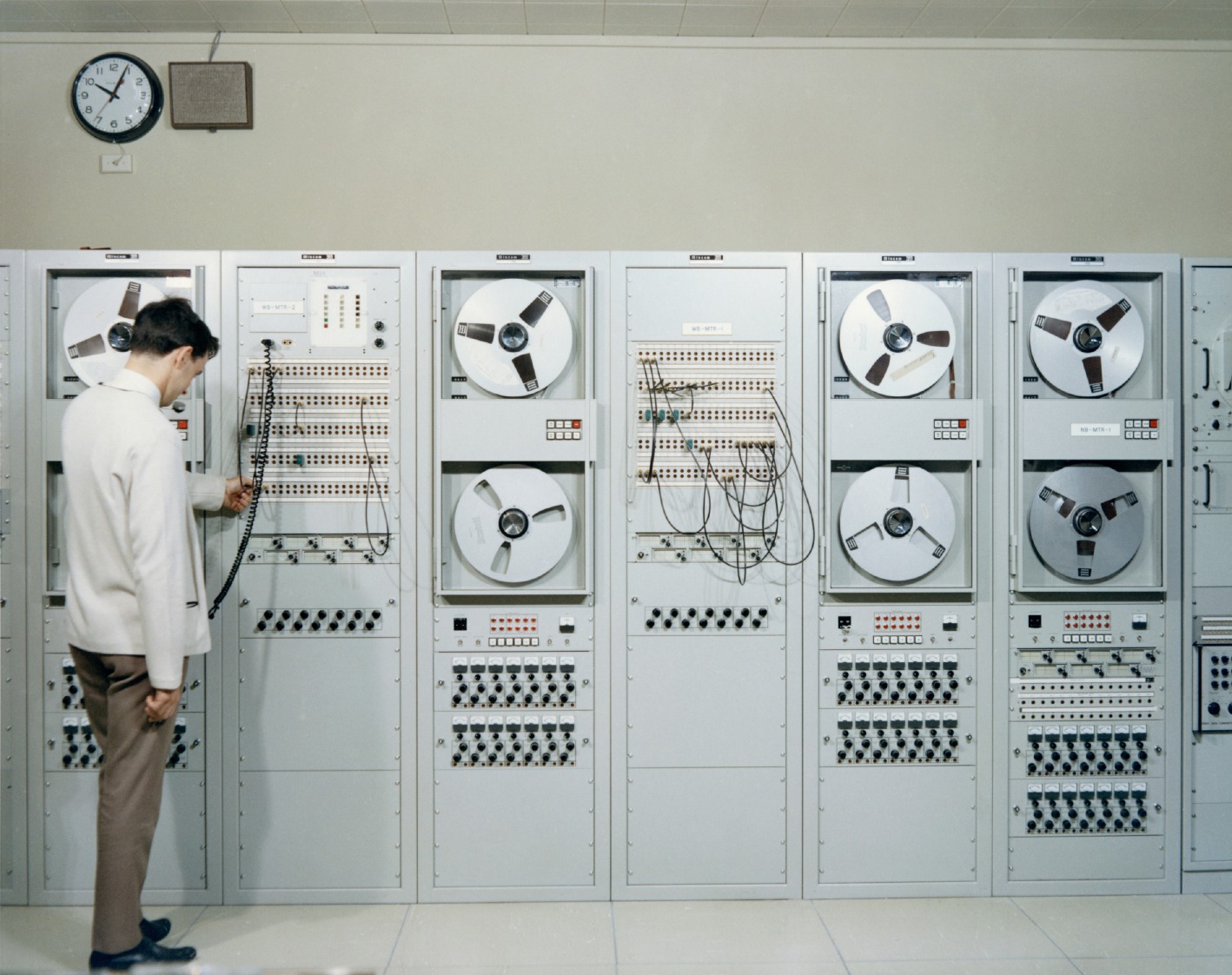
|
Analog reel-to-reel tape recorders for both wide and narrow band analog telemetry provided a means of raw data storage and playback during the mission operations support, station readiness testing and simulation/training exercises.
|
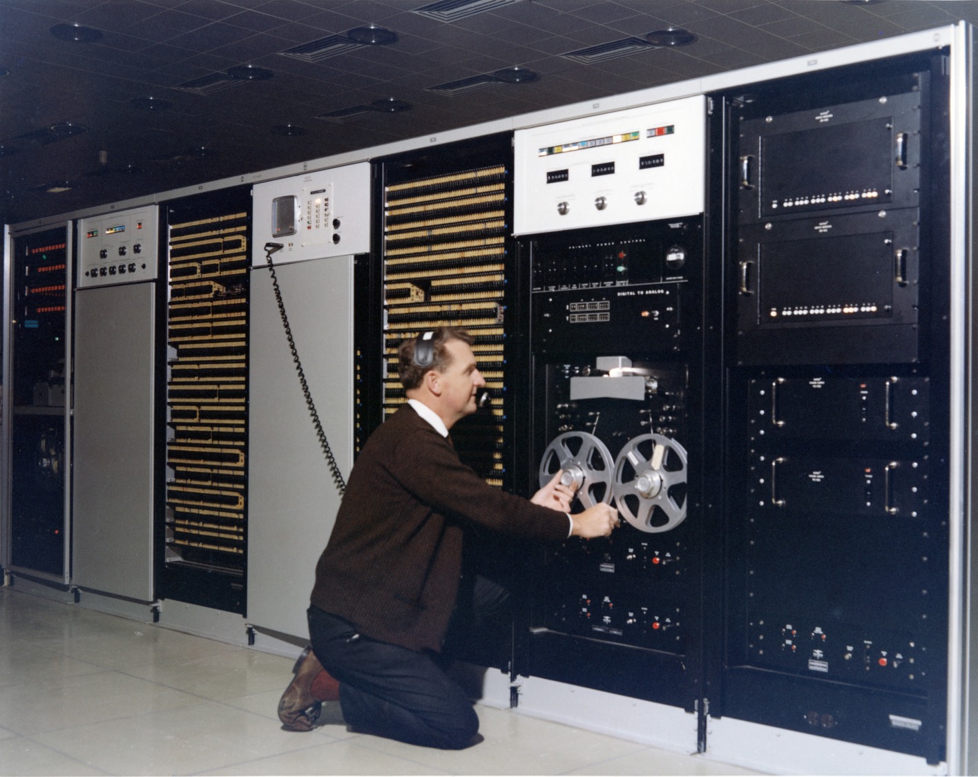
Bruce Withey at the Recorders.
Large, Larger.
Photo: Hamish Lindsay. Scan: Colin Mackellar.
From Tom Reid’s album, with thanks to John Saxon. |
PCM data was digitised and decomutated into predefined formats selected for specific phases of the mission before being sent to the telemetry (TLM) computer.
PAM processing received FM signals from the SDDS and passed them through the Digital Data Formatters (DDF) then onto the telemetry (TLM) computer.
Selected analog signals from the PAM processors as well as all of the stations receiver AGC parameters were digitised by a special purpose Analog Multiplexer Quantizer (AMQ) processor and sent to the TLM computer.
Simulators for both PAM and PCM data provided a means of testing from the subsystem level to fully integrated systems checking.
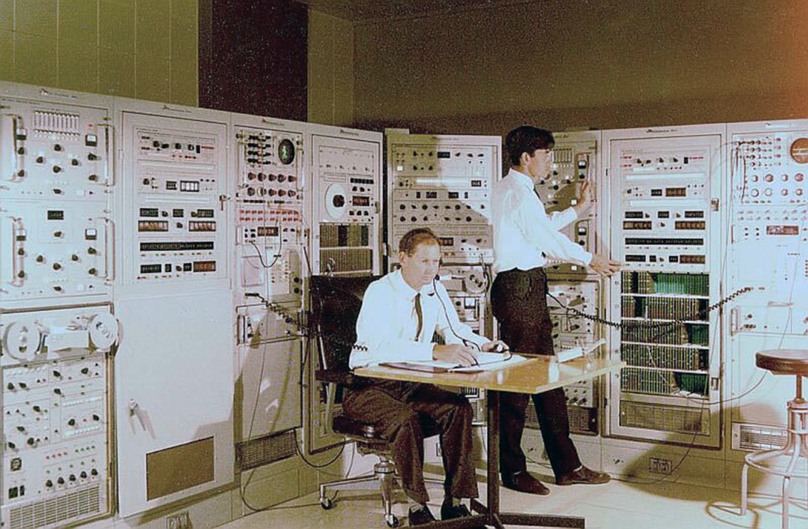
2.2) COMPUTER PROCESSING SECTION
|
Bryan Sullivan (seated) and Gordon Bendall (at the left hand Univac 642B computer) in the computer section in an early configuration of the Computer section.
Photo: Hamish Lindsay via John Saxon.
Image restoration Colin Mackellar. |
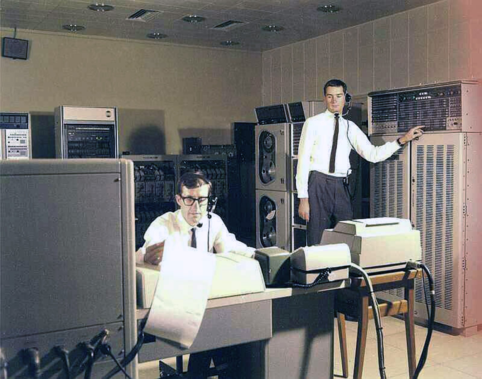
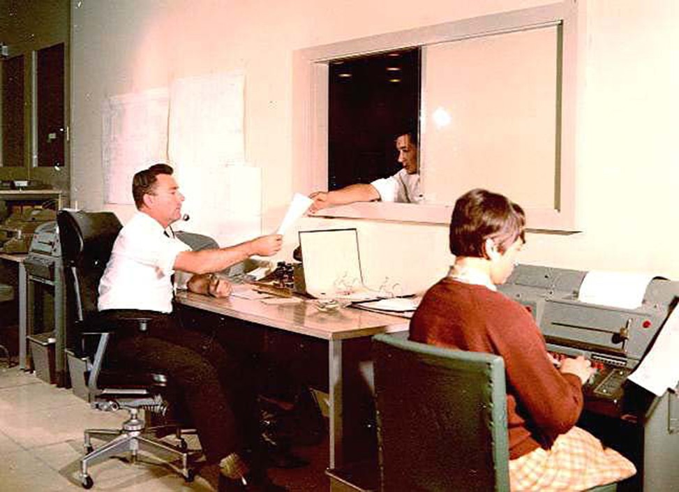
|
Taken at the same time as the photo above, Bryan Sullivan reads a printout, and Gordon Bendall stands at the other 642B.
Bryan writes (July 2018):
“The general purpose digital computers on the NASA Apollo tracking stations were initially programmed by the technical staff to diagnose engineering faults, as well as aid in the training and familiarisation with these UNIVAC computers and specialised peripheral equipment.
The printout (above) shows a listing of a program application (app.) written in the machine code format. Most locally produced software was written in machine code which used the most fundamental hardware instructions for manipulating internal and external data. Using this form of coding required a detailed knowledge of the computer hardware, engineering and design principles to effectively manipulate data. All the sequential steps in a calculation were carefully laid out in a flow chart form before coding was attempted.
Shown in the picture is a machine code listing of an app. with one instruction per line. All numbers are in binary coded octal (0 thru 7) notation format.
The first column is the exact physical address/location of each machine instruction in sequential order.
The second column is the machine code instruction along with its operand modifiers, index registers and I/O channel numbers.
The third column contained the operand such as a numerical constant, a variable or a physical address.
This machine coding was used on the NASA Apollo tracking stations until higher order languages, assemblers and compilers such as BASIC, FORTRAN and SYCOL were provided by UNIVAC.”
Photo: Hamish Lindsay. 2018 negative scan: Colin Mackellar.
(Older colour photo here.) |
GENERAL DESCRIPTION
Computer processing required four separate computers: CP1, CP2, CP3 and CP4 along with various associated peripheral units.
CP1 and CP2 systems were identical and symmetrical in their cabling and peripheral configuration. These two computers processed the spacecraft command and telemetry data. The two operational software applications (CMD and TLM) were interchangeable between computers with a minimum of cable reconfiguration. An Expanded Memory Unit (EMU) increased each computer’s memory capacity to a total of 64k words.
Spacecraft commands, sent from MCC, were normally received at the station via a high speed data line, validity checked and transmitted by the CMD computer to the USB section via an Up-Data Buffer (UDB) or special purpose modem and then onto the appropriate PA transmitter. Spacecraft commands could also be manually generated and sent using a special Computer Access Matrix (CAM) keyboard located on the Station Operations Console.
Spacecraft telemetry data was sent from the PAM, PCM and AMQ subsystems to the TLM computer. Due to the vast amount of telemetry data available, only a limited number of spacecraft parameters could be transmitted to Mission Control Center (MCC) due to capacity limitations of the external data lines of the worldwide NASCOM system. This permitted only selected data formats to be transmitted to the MCC in accordance with the predefined requirements of the mission flight plan. The output from the TLM computer, (30-bit parallel words) was converted to a serial bit stream of 4.8 kilobits per second and transmitted to the MCC over the external high-speed data lines.
An inter-computer channel provided a direct ultra high-speed data transfer path between the memory units of the CP1 and CP2 computers. These special channels were setup through standard UNIVAC engineering modifications. The ultra high-speed data transfer rates required that the physical inter-computer cable lengths be as short as possible. These unique I/O channel configurations eventually became known as a form of parallel processing where two or more central processing units shared a greatly expanded common memory system.
Magnetic tape was the primary external data storage medium for the computer systems. Both the CP1 and CP2 computers were duplexed (hard wired) to a controller with four tape handlers on each. With such a symmetrical physical configuration it meant that the operational software systems (CMD & TLM) could be quickly reconfigured with minimum switching or cable changing. Each individual tape handler’s logical address could be manually assigned via a switch which gave complete flexibility in assigning individual logical data types to any combination of physical tape handler address configurations.
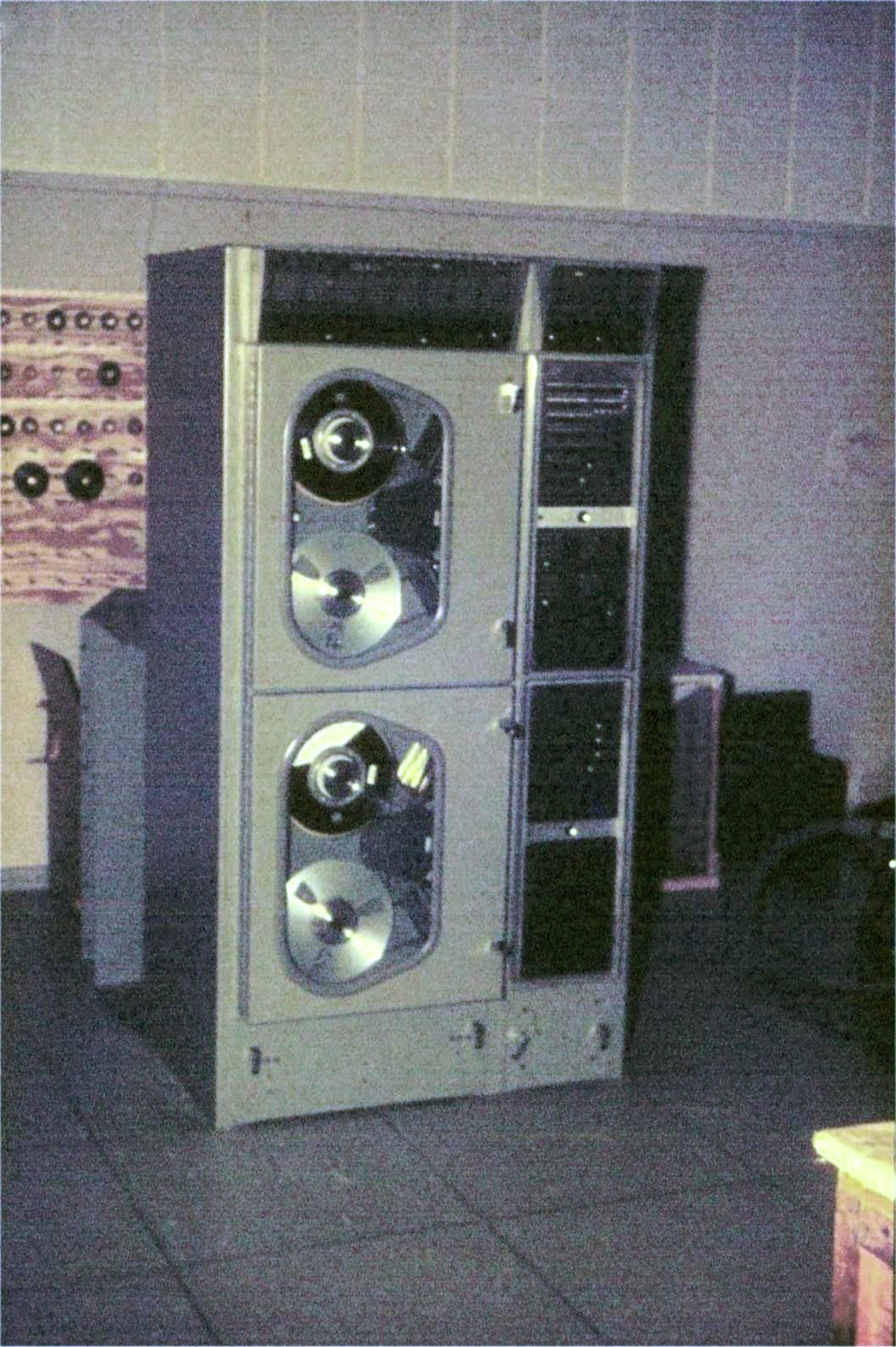
|
Univac Type 1540 Magnetic Tape Unit for the 642B computer.
Photo: Ian Hahn. |
CMD magnetic tapes included a Systems tape, Command History tape and a Recovery Fault/Log Dump tape.
TLM magnetic tapes included a Systems tape, a Recovery Fault/Log Dump tape and high speed output Data Log tape.
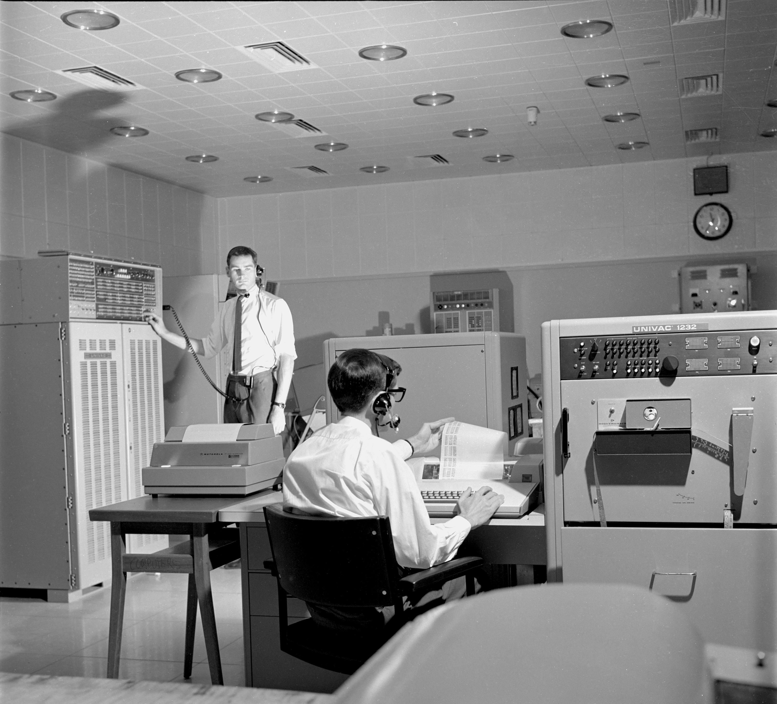
The CP3 (left) and CP4 (right) computers shared one magnetic tape controller with just two tape handlers.
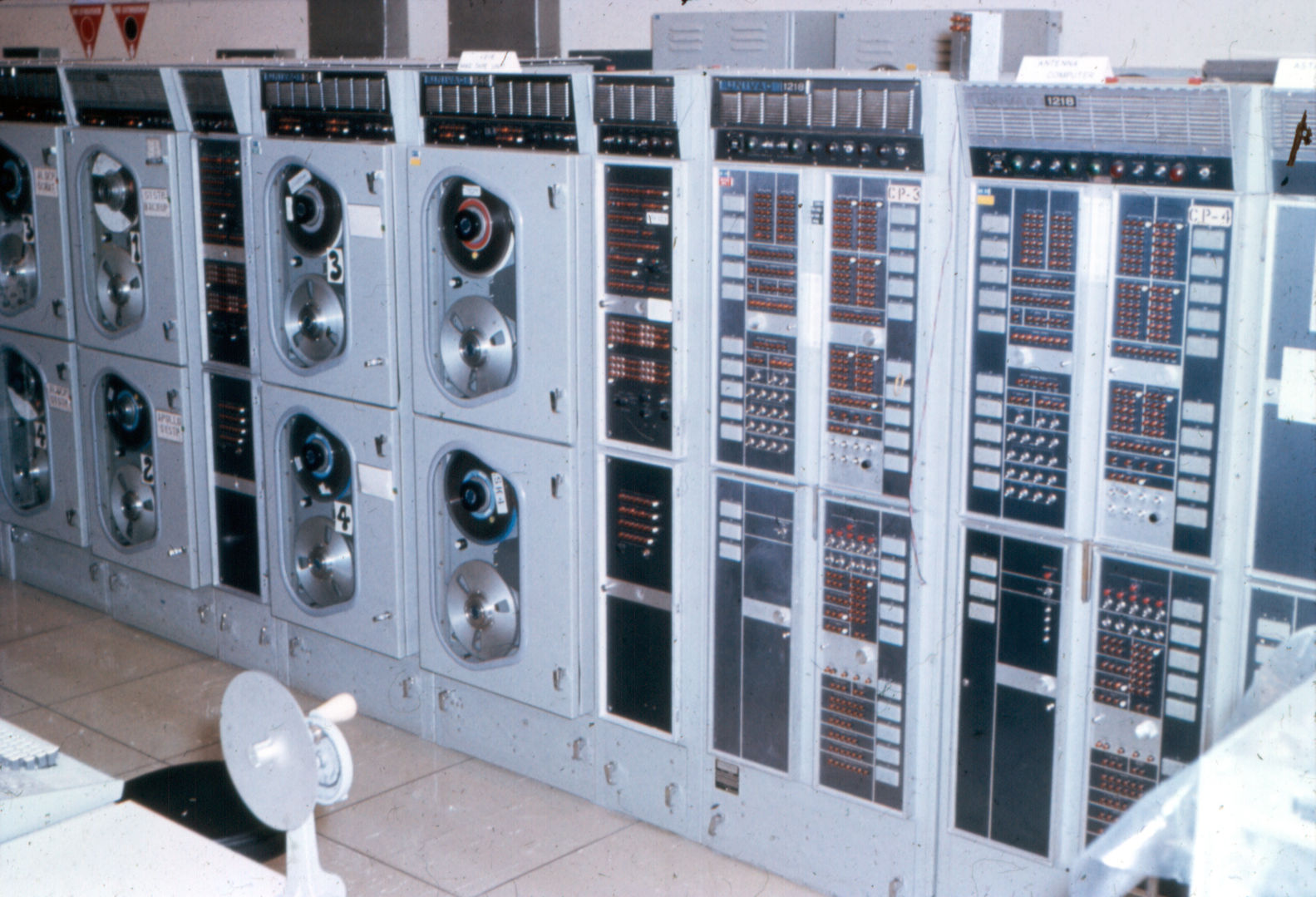
|
The 1218 area.
Large, Larger (2.6MB). Slide: Bryan Sullivan, scan Colin Mackellar. |
The CP3 system processed and generated pointing data for the tracking antenna which was received at the station in the form of a special teletype message and manually entered via the computer paper tape reader. The processed output on punched paper tape was an extrapolated series antenna positions representing a stepped track of the spacecraft’s flight path across the sky.
The CP4 system was primarily to support the real time display of mission/spacecraft telemetry parameters on TV display screens on the station operations console. The CP4 system also provided a backup to CP3 as well as a means of locally generating spacecraft command data for use in both mission simulation/exercises as well as a means of testing the integrated CMD system data flow.
Each of the four computer systems had a hard wired operators console consisting of a paper tape reader and punch unit as well as a keyboard and printer. Paper tape handling included five, seven and eight level formats. In addition to the operator’s consoles, CP1 and CP2 computers had hard wired automatic send/receive teletype (TTY) units which provided a low speed backup input for spacecraft command data in the event of a failure of a high speed NASCOM data line.
A unit called a Peripheral Communications System (PCS) housed additional peripheral controllers which were manually switched between the CMD and TLM systems whenever there was a need to reverse the configuration due to a hardware fault. Also contained within the PCS was an Interface System Adapter which performed three functions. One part controlled Computer Access Matrix (CAM) keyboard, the second controlled High Speed Printers (HSP) and the second was a digital buffer that received Greenwich Mean Time (GMT) in a parallel binary coded decimal format from the station time standard in the USB area for transfer to both the CP1 and CP2 computers with a one second granularity.
Three manually switched Data Transmission Units (DTU) converted parallel digital data into serial bit streams and visa versa. These digital bit streams carried telemetry and command data to and from Modems in the Communications Section.
Other peripheral units that were manually switched between the CMD and TLM systems were both UDBs, both PAM processors and the AMQ processor.
Operational software for the CMD and TLM systems was supplied from NASA’s Goddard Spaceflight Centre to each tracking station on magnetic tape. Other software for smaller programs was supplied on seven-level punched paper/mylar tape.
HARDWARE TECHNICAL DESCRIPTION 2
The four computers and the associated peripheral equipment met U.S. military ruggedized specifications and were supplied by UNIVAC, Division of Sperry Rand Corp. Being true ‘binary bit’, parallel, solid state, general purpose processors they were ideally suited to military and aerospace applications used in real-time 3 tactical tracking, command, control and simulation systems.
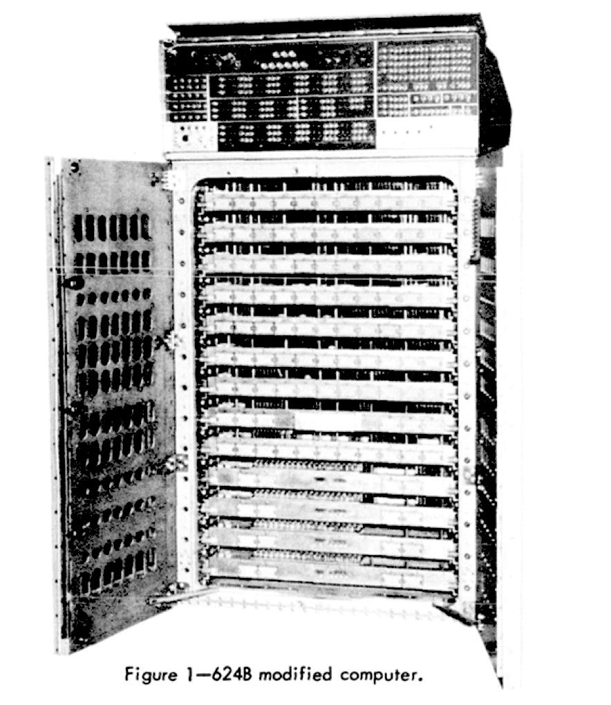
The CP1 and CP2 computers were UNIVAC type 1230 (CP-642B Modified) with a word size of 30 binary bits. They were physically identical with a random access memory capacity of 32k words each. An external Expansion Memory Unit (EMU) provided an additional 32k words for each computer. The computer on its own weighed 2300 lbs. (about one metric ton). It held 3400 printed circuit cards on thirteen horizontally mounted chassis.
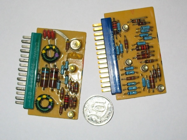
|
The UNIVAC printed circuit boards (PCB) were all identical in size, (70mm x 40mm), with a standard pin configuration.
Some boards had gold plated pins, others were silver. Each board with its discrete components was hermetically sealed in epoxy resin and consequently they were unrepairable on site. This PCB type was standard across the range UNIVAC military computers and associated peripheral devices at the time.
These PCBs provided a variety of logic gate functions as well as amplifiers, pulse generators, i/o line drivers and core memory drivers. In today’s PCs and LAPTOPS many thousands of these little PCBs are incorporated into a single thumb-nail size silicon chip.
Photo: Bryan Sullivan. See more printed circuit boards here. |
The first four chassis from the top were the I/O channel drivers followed by the I/O timing controller. Next was the CPU controller with main timing, then the arithmetic unit under. Next was the main memory controller above the four memory chassis containing the magnetic core stacks.
|
642B – from SP-87, page 182. |
Each computer had sixteen input and sixteen output channels while the EMU provided a further four input and four output channels to each computer.
The CP3 and CP4 computers were UNIVAC type 1218 (CP-789/UYK) with a word length of 18 binary bits. The CP3 computer had a memory capacity of 16k words and the CP4 had 32k words.
The magnetic tape units, UNIVAC Type 1540, consisted of one controller with four tape handlers per unit. They used standard ½ inch mylar tape operating at 800 frames per inch, 120 inches per second and were compatible with the IBM series 700 units. Both CP1 and CP2 had four tape handlers duplexed to each computer while CP3 and CP4 shared two tape handlers.
|
Close up of the Univac 1540 Magnetic Tape Unit.
Photo: Ian Hahn. |
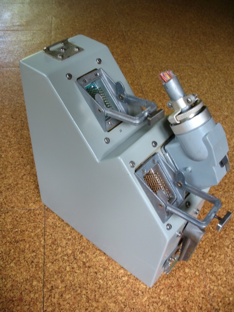
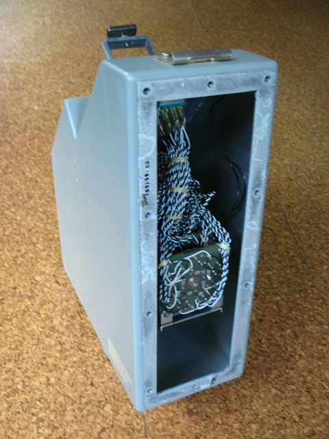
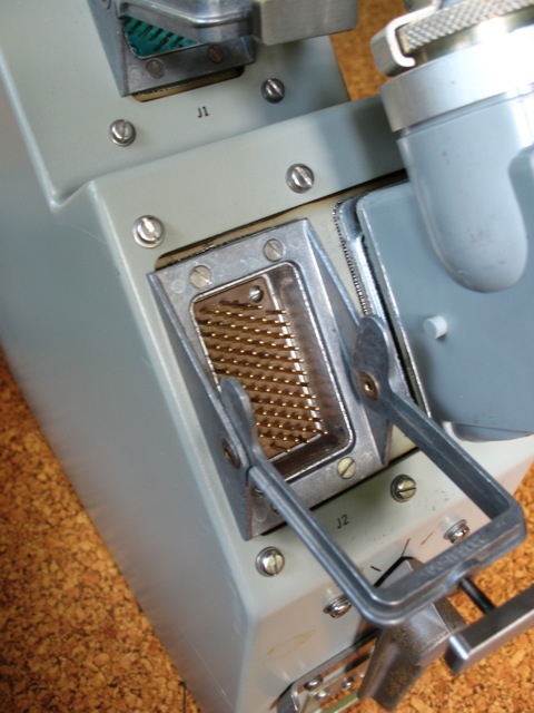
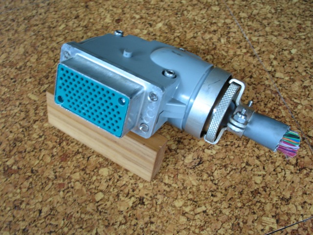
A major feature of the whole computer complex was the common input/output (I/O) user interface cabling arrangement. Each I/O channel used a ninety-way, shielded, one inch dia. cable to connect with each peripheral device. Two twisted-pair core conductors for each of the thirty parallel bits as well as the control bits for interrupt, request and acknowledge signals ensured interference free data transmission.
Another special feature of the interconnecting cabling was a switching rack (type 1299 Switch Board) consisting of groups of individual switch modules. Each module was a manually operated, sixty eight pole, three position switch. There were two racks of ten switch modules in each rack, which enabled rapid reconfiguration of peripherals.
|
The 1299 Switch rack is arrowed.
The computer room with John Saxon in the foreground and Geoff Ruck behind.
On the left is the Updata Buffer, the interface between
the Command Computer and the RF transmitters in the USB area, next are
the two Univac 642B computers with the Expanded Memory Unit between.
Further along the row are the Magnetic Tape Handlers
with the Univac 1218 computers at the far end.
Consoles with paper tape handlers, keyboards and teletypes
etc. to access the computers are down the centre.
Photo and text: Hamish Lindsay. |
 |
|
|
|
| Bryan Sullivan took these photos of a 1299 switch unit he conserved. |
The CP1 and CP2 type computers each had a separate input/output (I/O) hardware timing chain which ran independently of the main processor timing chain. This allowed input or output memory buffer areas to continually transfer data independently of the running of the main application software. This feature enabled system restart and recovery operations to occur without affecting the continuous flow of telemetry information.
Operator control panels on each computer provided a vast array of illuminated push button switches giving the operator access to all of the internal registers and status functions. A set of six special jump and stop keys allowed the operator to control pre-programed portions or functions of the operational/application software.
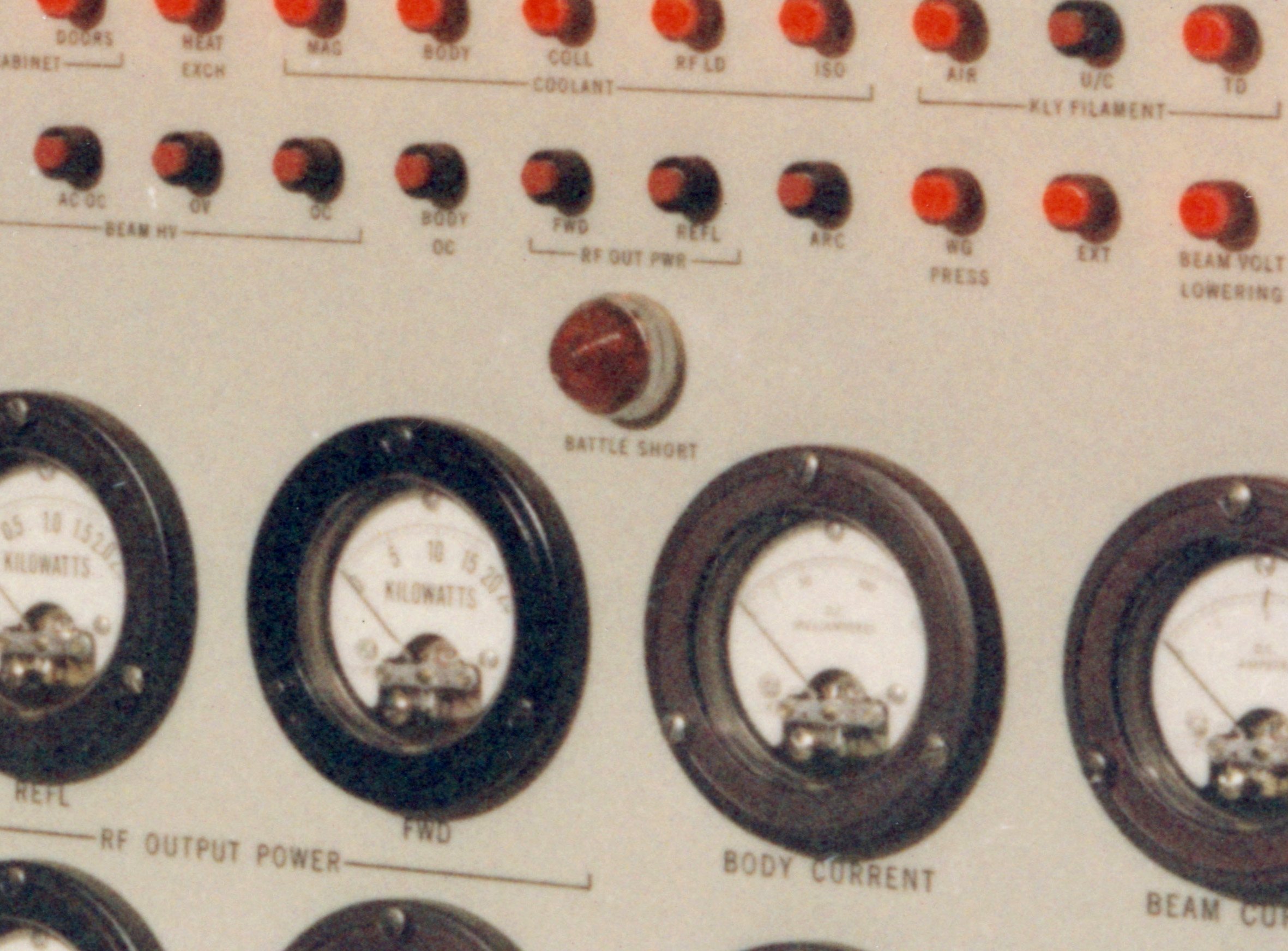
Each computer, being of the militarized type, was fitted with a special control panel switch labeled ‘battle short’. When selected, the battle short function bypassed all of the safety features such as under voltage, over voltage, high temperature, and cooling fan failure conditions. The battle short switches were used for very short time periods during certain Apollo mission critical events or maneuvers e.g. Apollo 8 Lunar Orbit Insertion (LOI).
|
“Battle Shorts” were also installed on other vital equipment.
Photo: The Battle Short indicator on one of the Power Amplifier consoles at Honeysuckle Creek.
 Hear NASA Public Affairs commentator referring to Battle Shorts across the MSFN – 15 minutes before the Apollo 11 lunar ascent. (250kb mp3 file. Audio courtesy John Stoll at the Johnson Space Center.) Hear NASA Public Affairs commentator referring to Battle Shorts across the MSFN – 15 minutes before the Apollo 11 lunar ascent. (250kb mp3 file. Audio courtesy John Stoll at the Johnson Space Center.)
Scan and audio clip: Colin Mackellar. Detail from this photo. |
All computers were supplied with magnetic core memory. A switch on the operators control panel enabled memory to be operated on high, normal or low voltage margins. When operated on voltage margins in conjunction with diagnostic software, any potential memory component failures were usually highlighted well in advance. A standard memory diagnostic software program, called ‘BRAINWASH’, was very versatile in writing and reading back various combinations of binary ‘ones’ and ‘zeros’ in fixed or random patterns while progressively relocating itself to operate and test all of the total computer memory compliment.
Power supply for each military computer system required the American Standard 115 Volt, 3 phase, 60 Hertz which was provided by individual remote controlled rotary converters situated in the building basement.
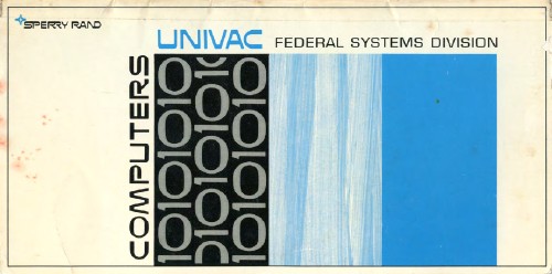
|
Bryan preserved this brochure showing the range of UNIVAC computers. He obtained this copy while on a training course at Glendale, California, in January 1969.
Click the image to download a 3.4MB PDF file. |
3.) COMMUNICATIONS SECTION
The communications centre was like a large office containing an array of teletype (TTY) machines (ASR model 35s) and several tall racks of technical equipment including line testing gear, jack fields and high speed modems.
|
Martin Geasley (left) in the Comms Room passes a message through the window to the Ops Console. Probably late 1966.
Photo: Hamish Lindsay – via John Saxon. |
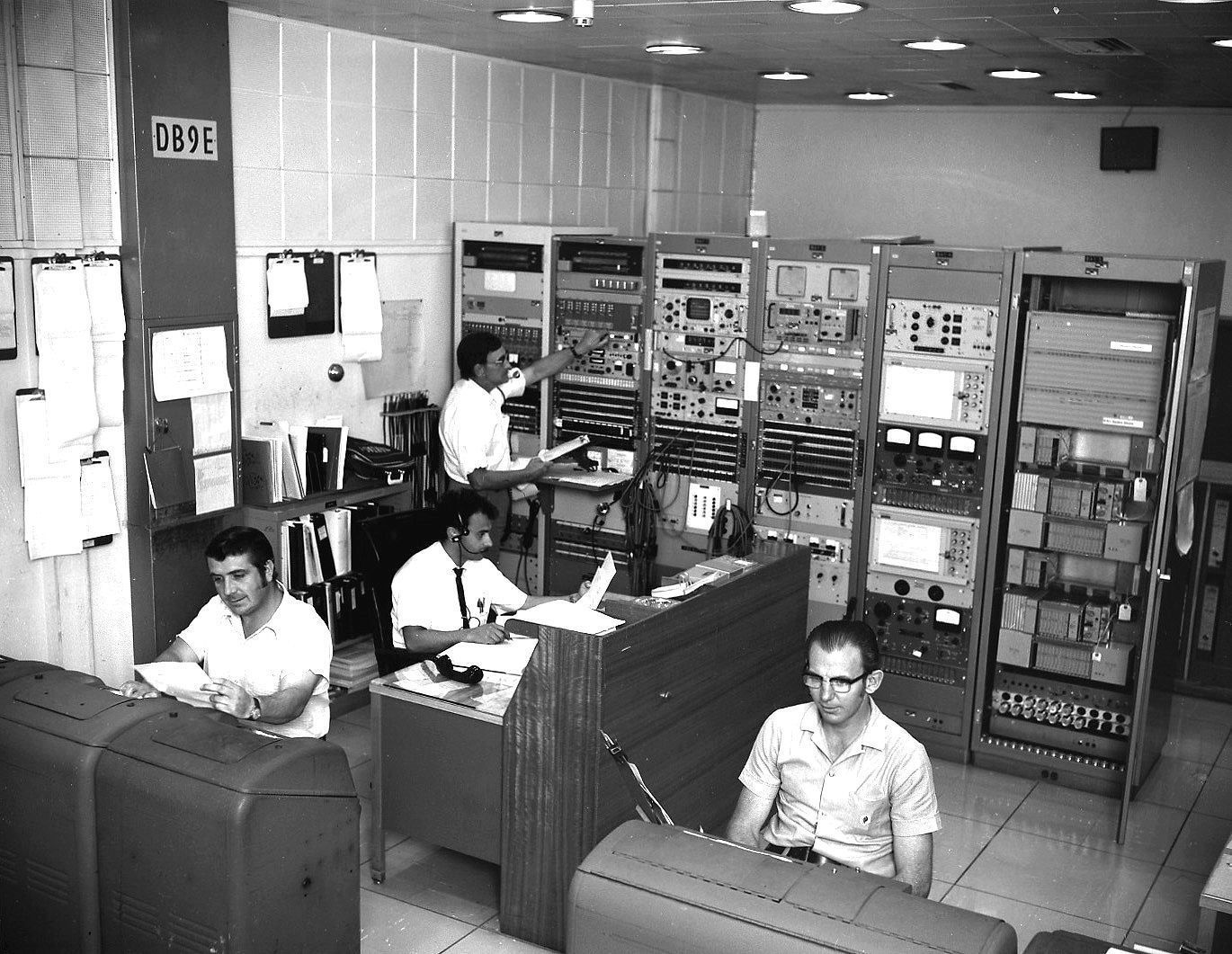
|
The Communication Section in action in Apollo days.
Here Dick Stubbs,
left foreground and Charlie Collins, right foreground, are sending
teletype messages, while Tony Gerada is sitting at the operations
console in the centre. Fred Hill [Comms Tech] is monitoring the
switching and patch panel behind.”
Photo and notes: Hamish Lindsay. |
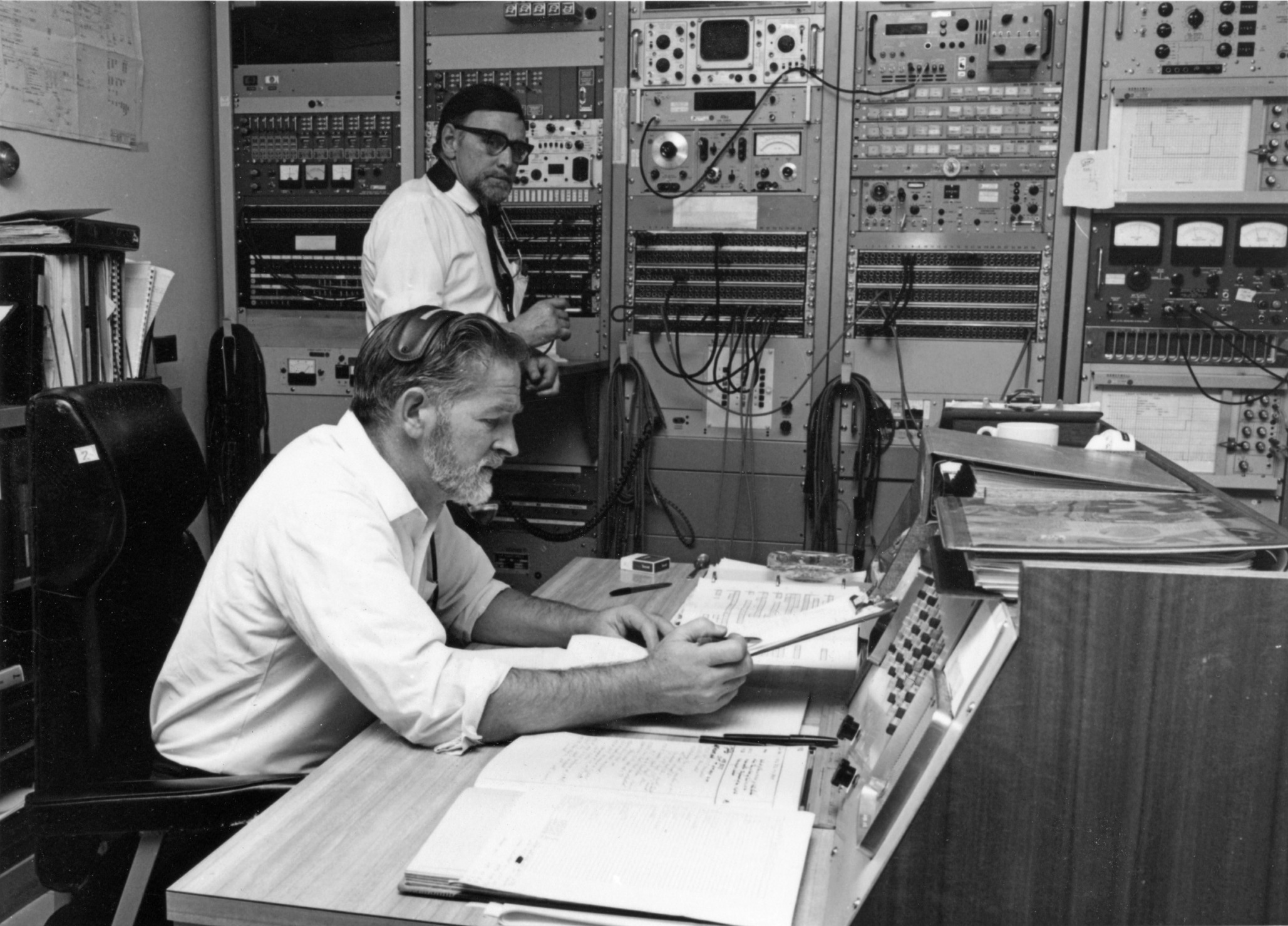
|
Keith Hiscock (foreground) and Fred Hill at the low speed testing rack in the Comms Centre.
Taken just before Apollo 11.
Photo: Australian News and Information Service.
Scan: Colin Mackellar. From Tom Reid’s album. |
Line testing gear consisted of a ‘number comparison’ test set for low speed (TTY) lines and bit error rate testing equipment for the high speed modem lines.
|
Bob Campbell in the Comms Section working on a teletype machine.
Photo: Hamish Lindsay. |
High speed data modems of the time (4.8 kBPS) were heavy rack mounted units about the size and weight of a full filing cabinet drawer.
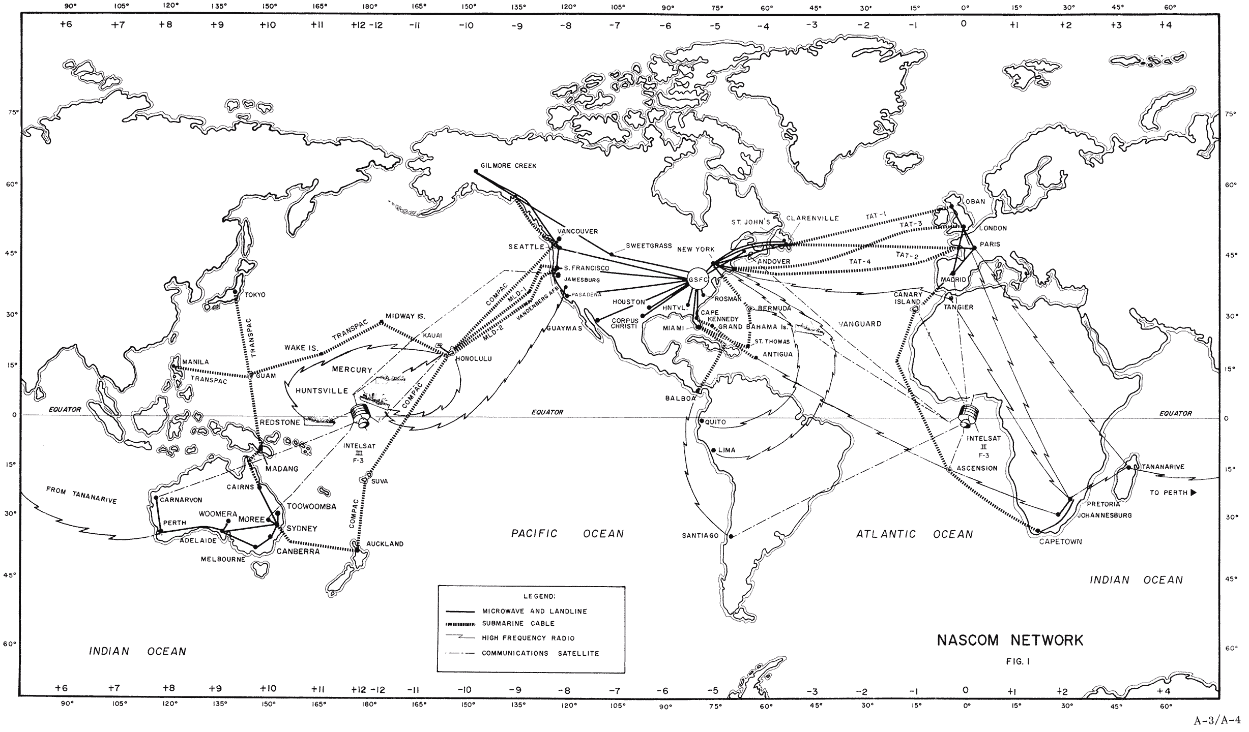
The station was connected to the outside world of NASA Communications (NASCOM) by six high-speed data (HSD) lines and two low-speed Teletype (TTY) lines.
The HSD lines 1, 2 & 3 carried voice communications:
1 for astronauts air/ground,
2 for voice coordination between stations and mission control centre (MCC) and
3 for engineering/technical discussions between stations and MCC/Goddard Spaceflight Centre (GSFC).
Lines 4, 5, & 6 carried digital data to and from stations and the world wide NASCOM hub at GSFC.
Several super broadband lines transferred live tracking/telemetry/command data between the GSFC to the MCC in Houston, Texas.
The two low-speed A & B circuits (lines) carried both operations and administrative TTY traffic as well as special formatted tracking and command data formats.
|
The NASCOM Network for Apollo 11.
Preserved and scanned by Bryan Sullivan. More here.
|
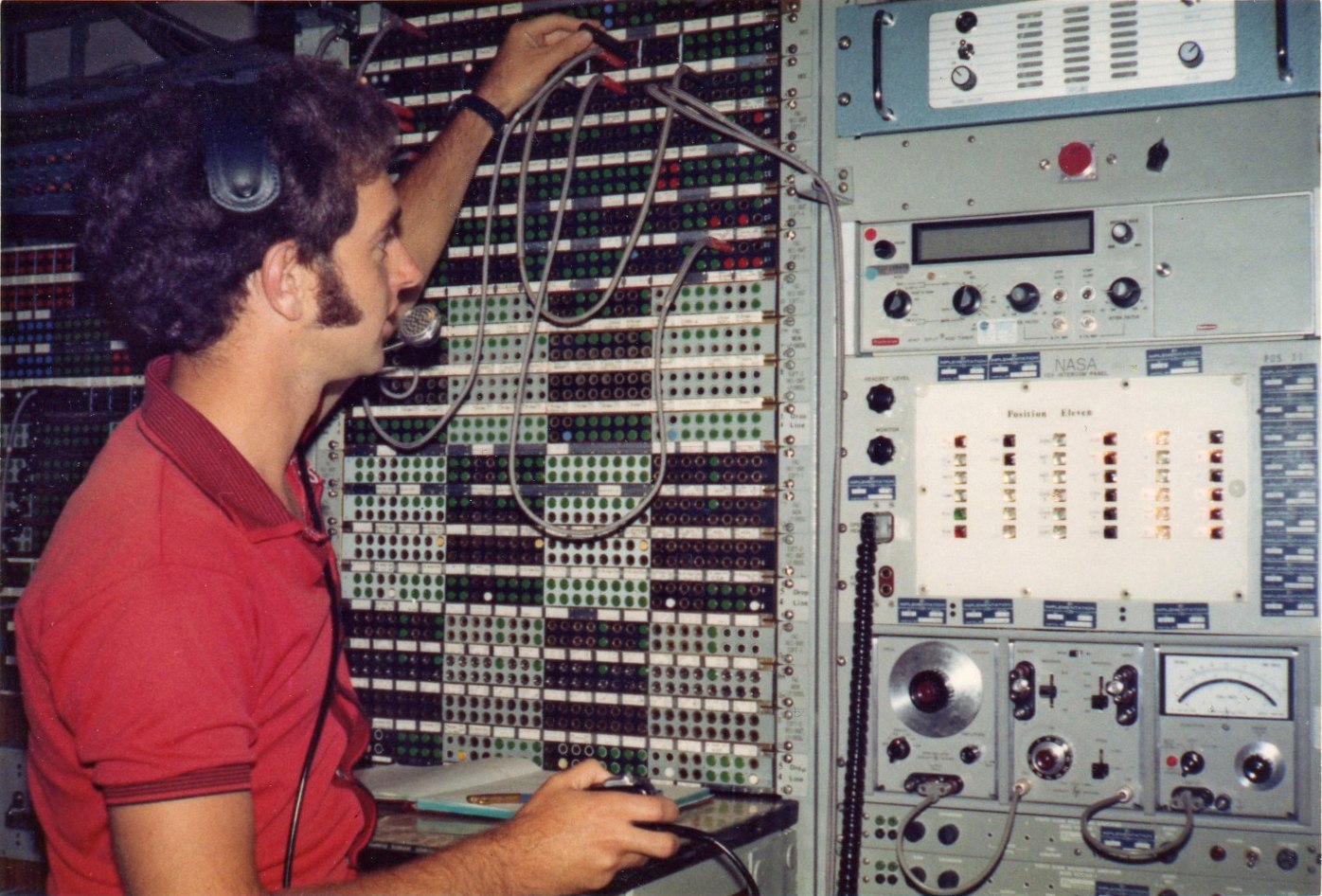
The Communications Centre had a further annex or ‘wire room’ predominantly occupied by several rows of rack mounted ‘telephone’ type equipment which was the station’s internal intercom (112A Key) system. All operations staff were ‘connected’ through the use of a headset and microphone. Various operator positions had access to combinations of eight ‘loops’ or voice channels: (A thru H) or ‘alpha, bravo, charlie, delta, echo, foxtrot, golf, hotel’.
|
Stirling Finlay in the Wire Room c. 1973. Scan: Stirling Finlay.
Larger, Larger. |
The first three loops were available to all operator positions while the remaining five loops were for use within the various sections. The alpha loop was the primary reporting and coordination loop for operational conversations. The bravo loop was for engineering and technical discussion. The charlie loop was an alternate to the alpha loop and usually coordinated operational matters pertaining to telemetry and computer data.
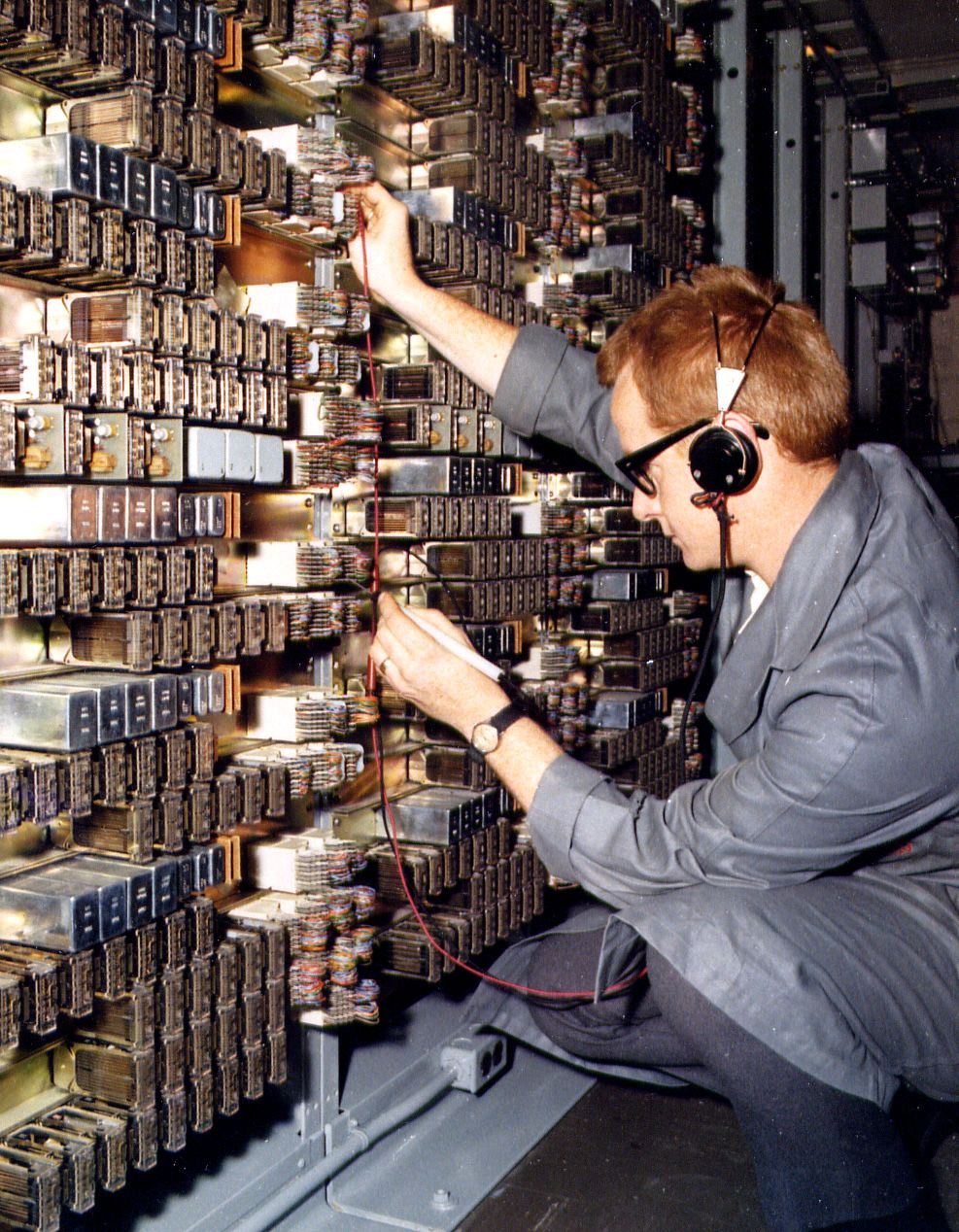
|
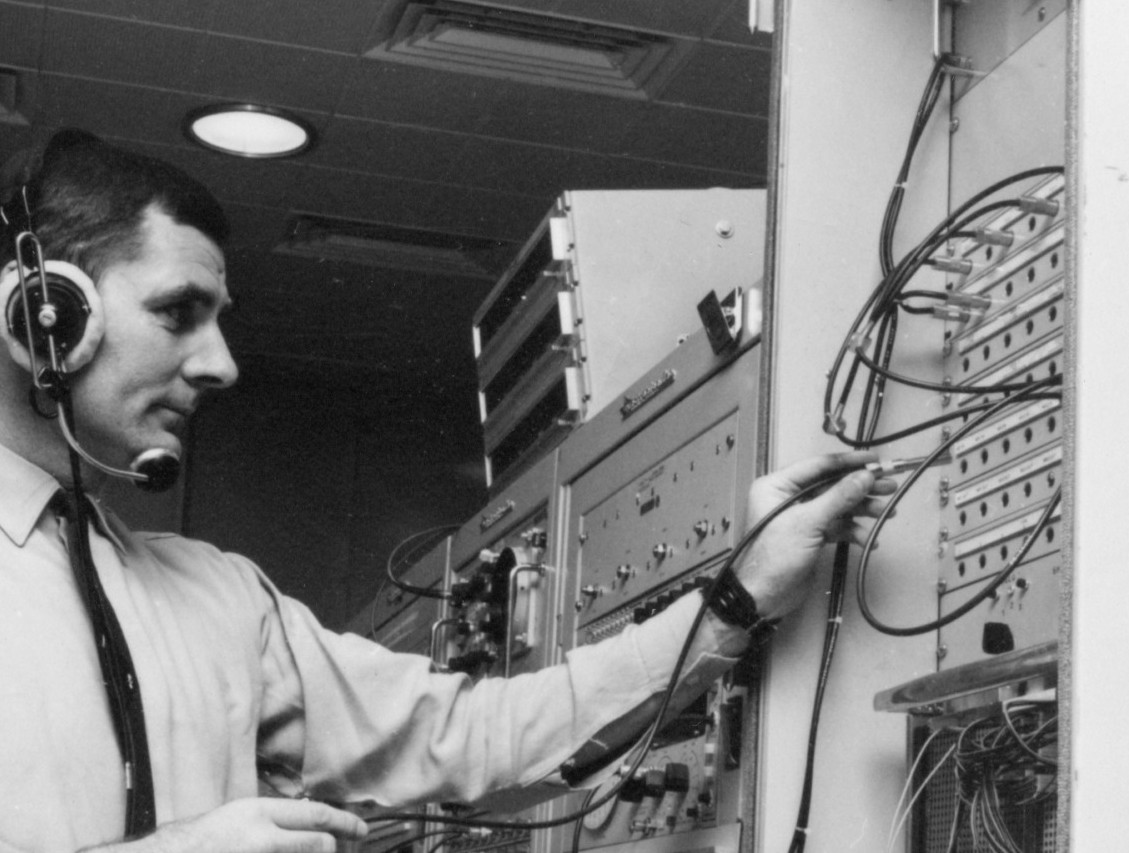
John Noonan in the early Apollo days chasing through a fault in the station communication
system relays. Photo:
Hamish Lindsay. |
|
David Ralph in the Wire Room.
Large, Larger.
Photo: Australian News and Information Service.
Scan: Colin Mackellar. From Tom Reid’s album. |
The Wire Room also contained the terminal equipment for the broadband microwave link to the Tidbinbilla Tracking Station twenty kilometers away to the north. This broadband link carried primarily the spacecraft demodulated subcarrier signals, astronaut air/ground voice, video (TV) as well as internal intercom, public address and other miscellaneous communications to and from the two stations.
|
Collins Microwave and Wideband Rack during the Deep Space era.
Large, Larger.
Photo from the Tidbinbilla archives. Scan: Colin Mackellar. |
|
The Honeysuckle Creek microwave link tower configured for Apollo 11.
The main link to Tidbinbilla (via a passive repeater on Dead Man’s Hill) is the large dish facing the camera.
The small dishes were PMG TV link and ABC outside broadcasting dishes pointing to Willamsdale PMG microwave tower for Apollo 11.
Frame from ABC-TV footage, July 1969. |
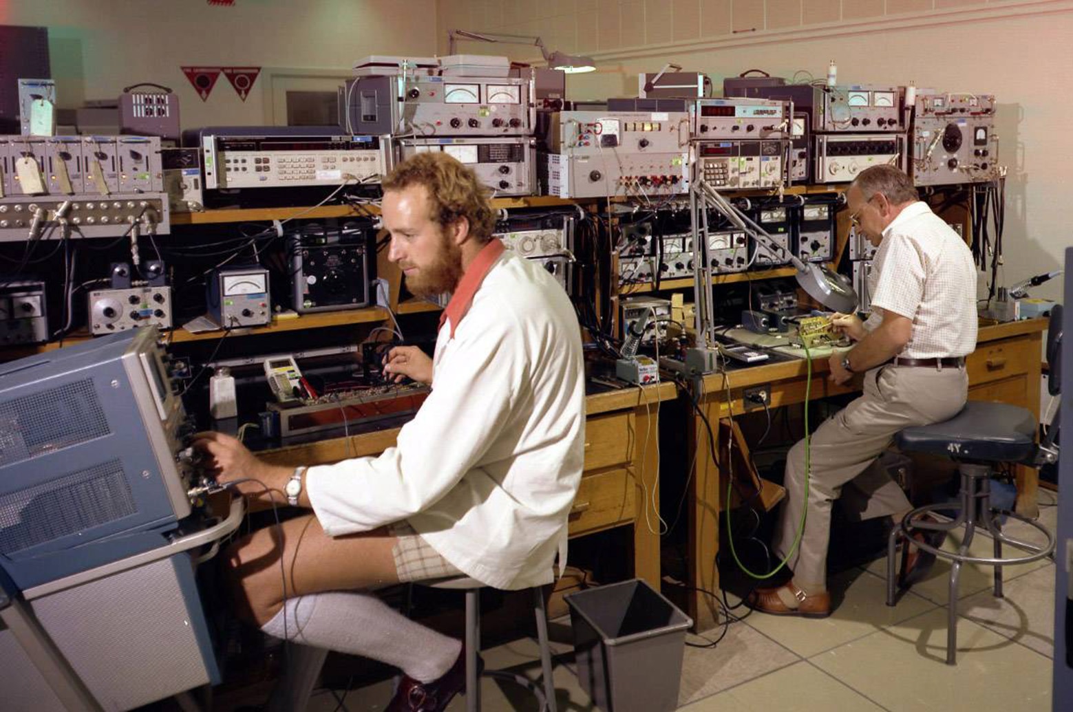
TEST EQUIPMENT
The test equipment lab., part of the Technical Support Section, carried out not only instrument repairs but regular equipment calibration as required by NASA engineering procedures.
A vast array of highly specialised, oscilloscopes, signal generators, spectrum analysers etc., were just a few of the many precision instruments or ‘tools-of-trade’ that were used by the engineers and technicians on a tracking station.
|
Wally Smallwood in the Test Equipment Section in the early days before the opening, probably late 1966. Photo: Hamish Lindsay. |
|
Dean Gilkes (left) and Terry Hearn in the Test Equipment Section.
Photo: Hamish Lindsay. |
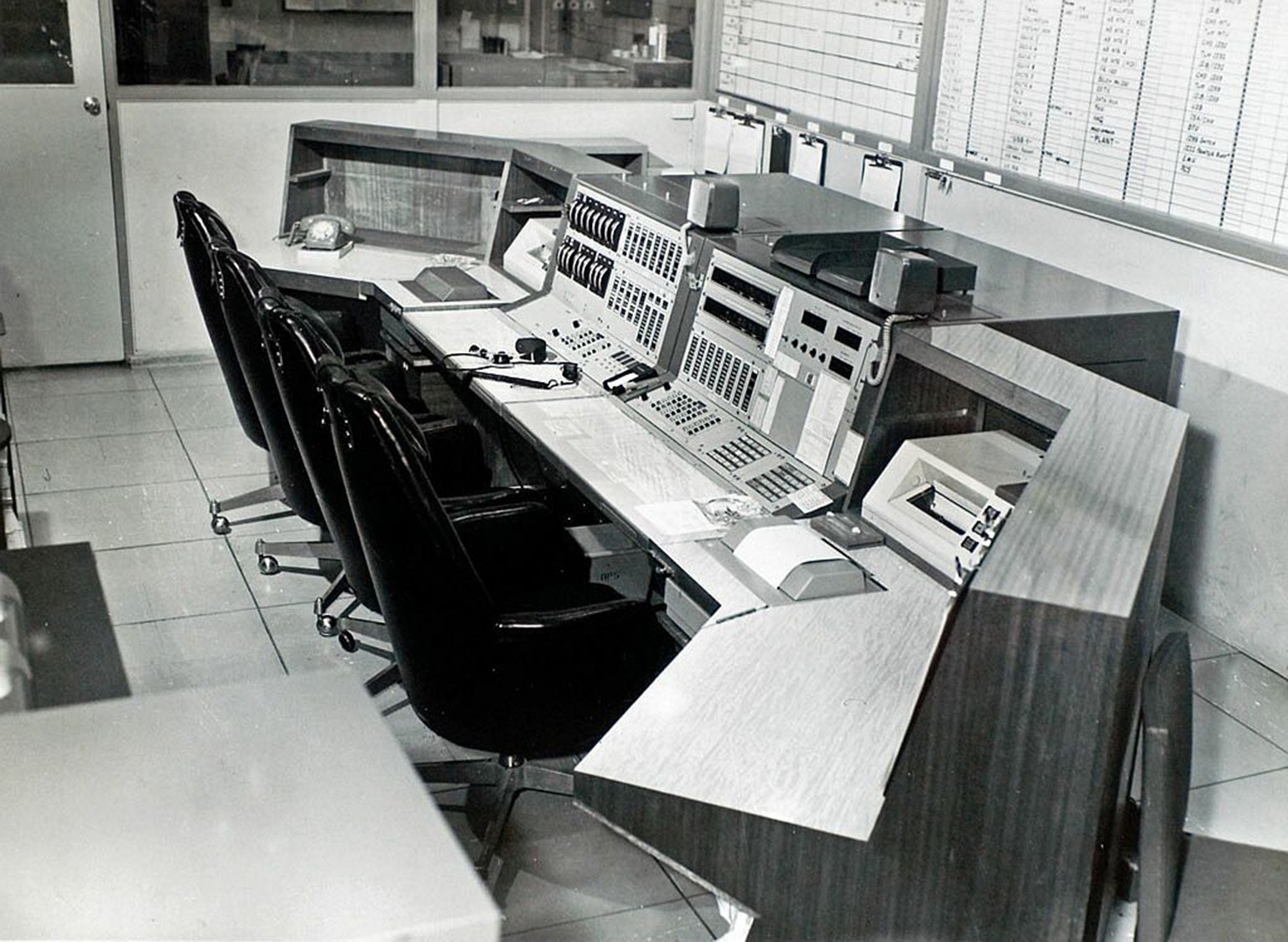
4.) OPERATIONS SECTION
All station operations were conducted from two adjoining consoles located in a room between the computer area and the communications center.
The left hand console was operated by a senior managerial person, referred to as OPS1, responsible for all operations relating to tracking, signal reception, signal subcarrier processing and other subsystems of the USB area.
The right hand console was manned by a senior staff member, referred to as OPS2, responsible for the data processing of all telemetry, command and voice communications entering and leaving the station.
Each console was equipped with an array of meters and indicator lights representing the status of the various data flow paths, a display of the station’s configuration, a computer keyboard matrix as well a comprehensive access to all station intercomm loops and spacecraft uplink and downlink voice communications.
These two staff functions tied all of the station’s operations activities together and supervised the mission support operations, readiness testing and simulation exercises as well as the coordination with GSFC and MCC personnel.
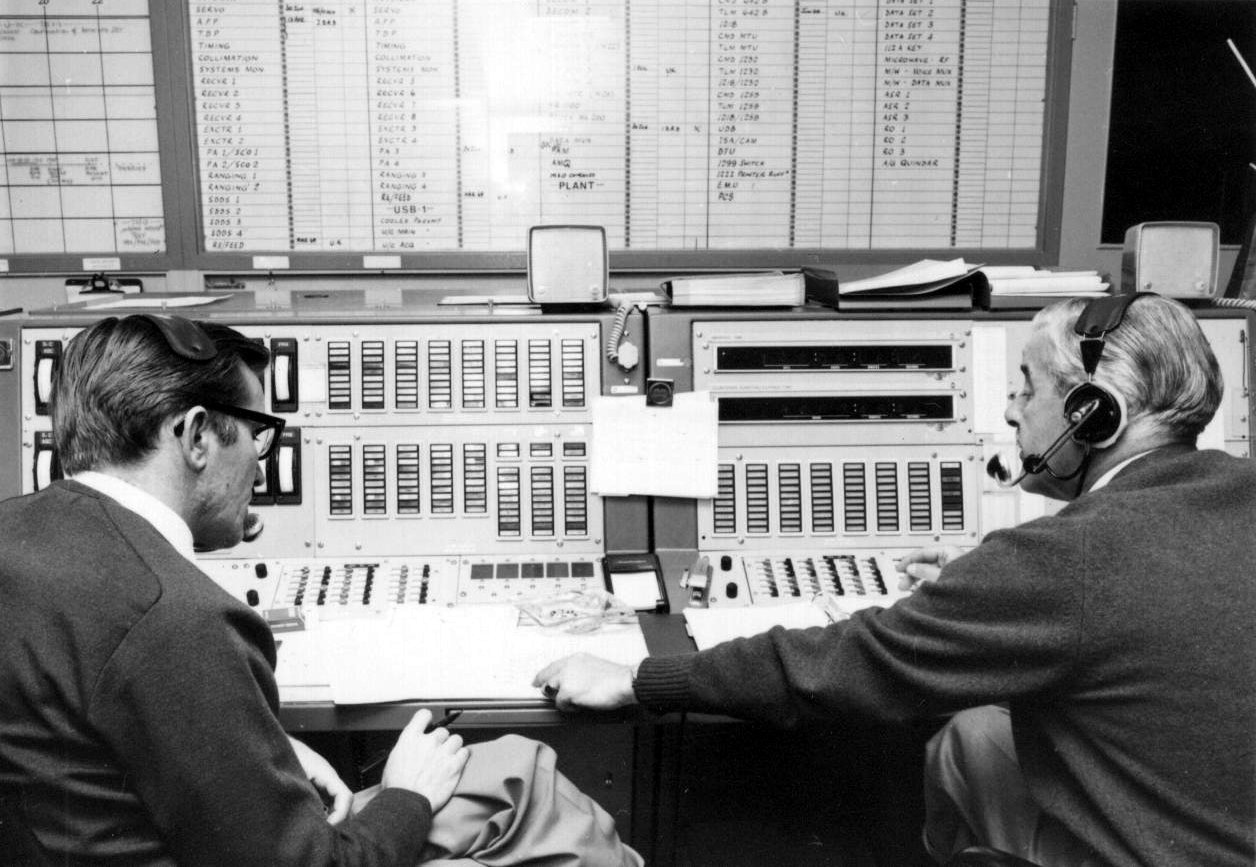
|
Ops Supervisors John Saxon and Ken Lee at the Operations Console.
Photo: Hamish Lindsay, via Martin Geasley.
|
|
Station Director Tom Reid and Operations Supervisor Ken Lee seated at the Operations Console.
Photo: Australian News and Information Bureau, 11 July 1969. Scan: Ed von Renouard. |
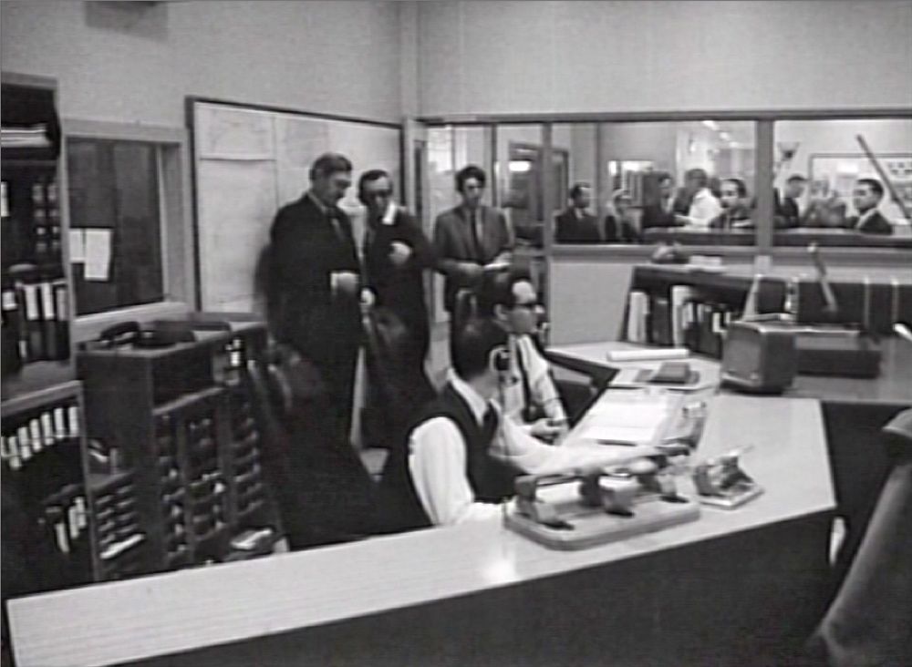
Directly behind the operators was a small sliding glass window into the communications centre. This enabled the many operational TTY messages to be passed directly to/from the OPS1/OPS2 supervisors. Typical high priority TTY messages included the Site Configuration Message (SCM), prediction of the 29 sky track points between acquisition and loss of signal (AOS and LOS) times (referred to as the ‘29-Pointer’) and the Station Status Reports.
|
The window from the Ops Console to the Comms Centre is seen in this footage of Prime Minister Gorton’s visit on 21 July 1969.
John Saxon and Ian Grant are seated at the Ops Console. StaDir Tom Reid explains to the Prime Minister.
Australian Broadcasting Commission news footage. |
5.) STATION SIMULATION SYSTEM
A Station Simulation System was designed and assembled by the technical staff at Honeysuckle for the purposes of operator training as well as carrying out quick pre-track signal and data flow checks. A dedicated simulation room in which a large console housed all of the electronic signal and voice communications equipment as well as a computer console separated the simulation operations team (Sim.Team) from the normal station operations.
The simulation system simultaneously generated all of the various downlinked signals from each Apollo spacecraft including the astronauts’ life support backpacks as well as signals from the lunar rover vehicle.
Voice communications with the Sim. Team allowed for realistic conversation between astronauts, the MCC and the station. Complete realism was never fully achieved without the true American accents.
A computer console in conjunction with the CP-4 computer provided a means of simulating digital command data ‘originating’ from the MCC and being uplinked to the spacecraft via the station’s normal command data flow path.
The simulated S-Band signal from the Sim. System was able to be inserted via the USB Test Inject network or via the ‘near’ Collimation Tower. The latter was more preferable, of course, being without any hard connection. This also provided a more realistic test using the main dish or the acquisition antenna. The simulation system also provided a quick antenna tracking and data flow check prior to station acquisition of signal (AOS) of the spacecraft tracking period.
6.) TECHNICAL SUPPORT SECTION
The Technical Support Section (TSS) maintained all the station’s documentation including technical and engineering manuals, drawings, drafting, general and archival filing etc. as well as the Test Equipment Section.
Operational documentation updating became a large part of the TSS work activity especially during Apollo missions. The tracking stations went onto ‘mission status’ several weeks before the launch date.
|
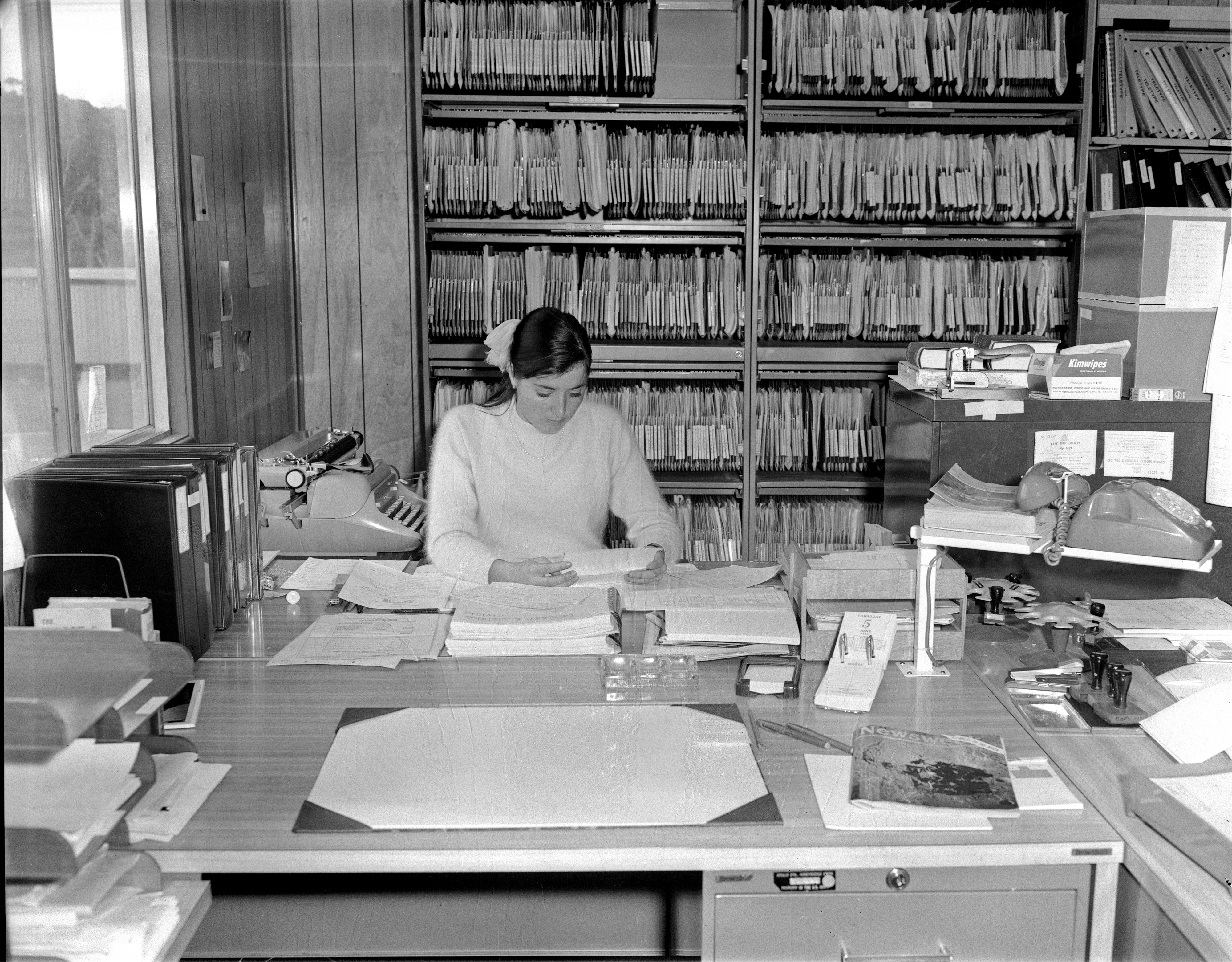
Jenny Hame was one of the early TSS secretaries. Behind
her are the station files, mainly copies of all the TWXs sorted into the station sections or subjects.
The desk calendar reads Thursday 5 June 1969.
Photo:
Hamish Lindsay. Scan: Colin Mackellar.
|
As the countdown progressed, operations procedures manuals required updating frequently and as fast as possible. Changes to the operations procedures arrived via teletype (TTY), usually over-night (being daylight in the U.S.). The TSS clerical staff would literally do a ‘cut and paste’ from the TTY printout directly into the affected manuals and rush the page copies around to all of the operations sections. Formal updated pages usually arrived via express air-mail a few days later.
|
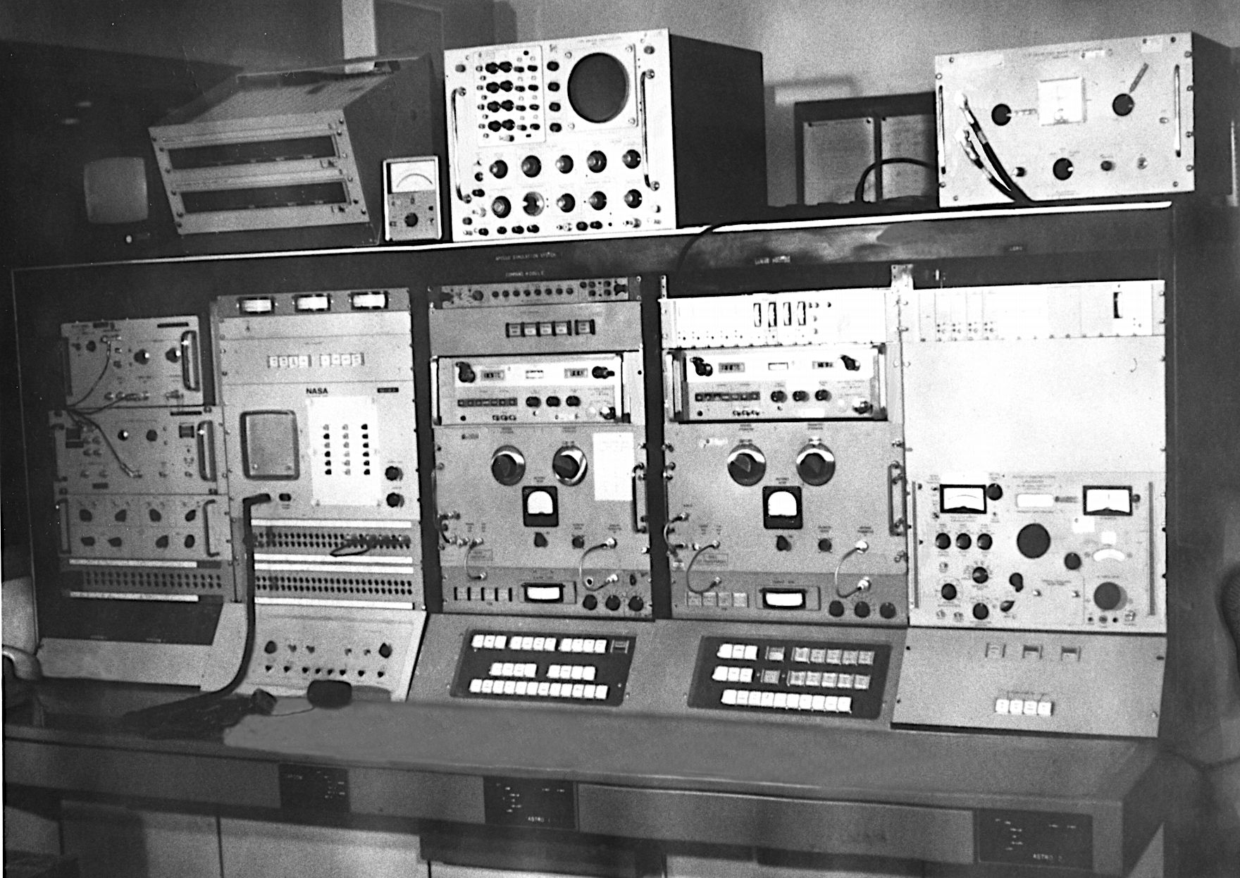
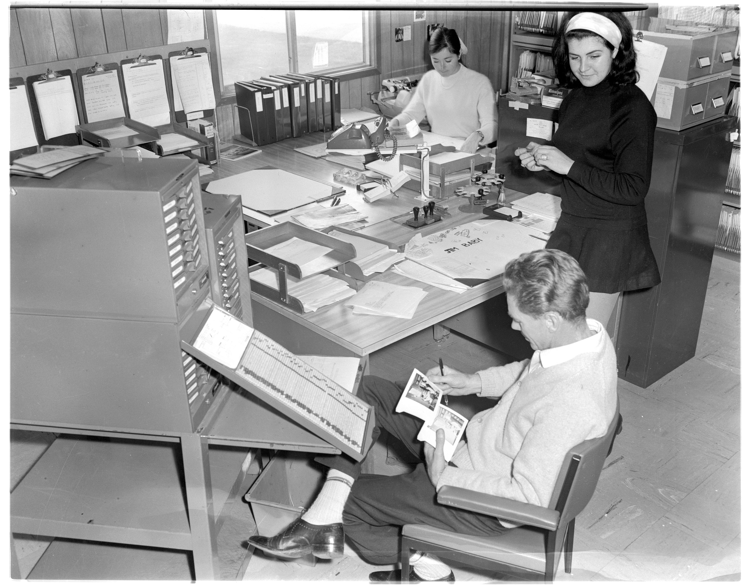
In the TSS building, “Dutchy” Jim Holland examines Polaroid composition shots while Jenny Hame works at the back. (Can anyone please identify the girl on the right?)
Hamish Lindsay writes, “To Jim’s left is the EI (Engineering Instruction or equipment modification) status drawers behind which was my desk.”
Photo:
Hamish Lindsay. Negative scan: Colin Mackellar.
|
|
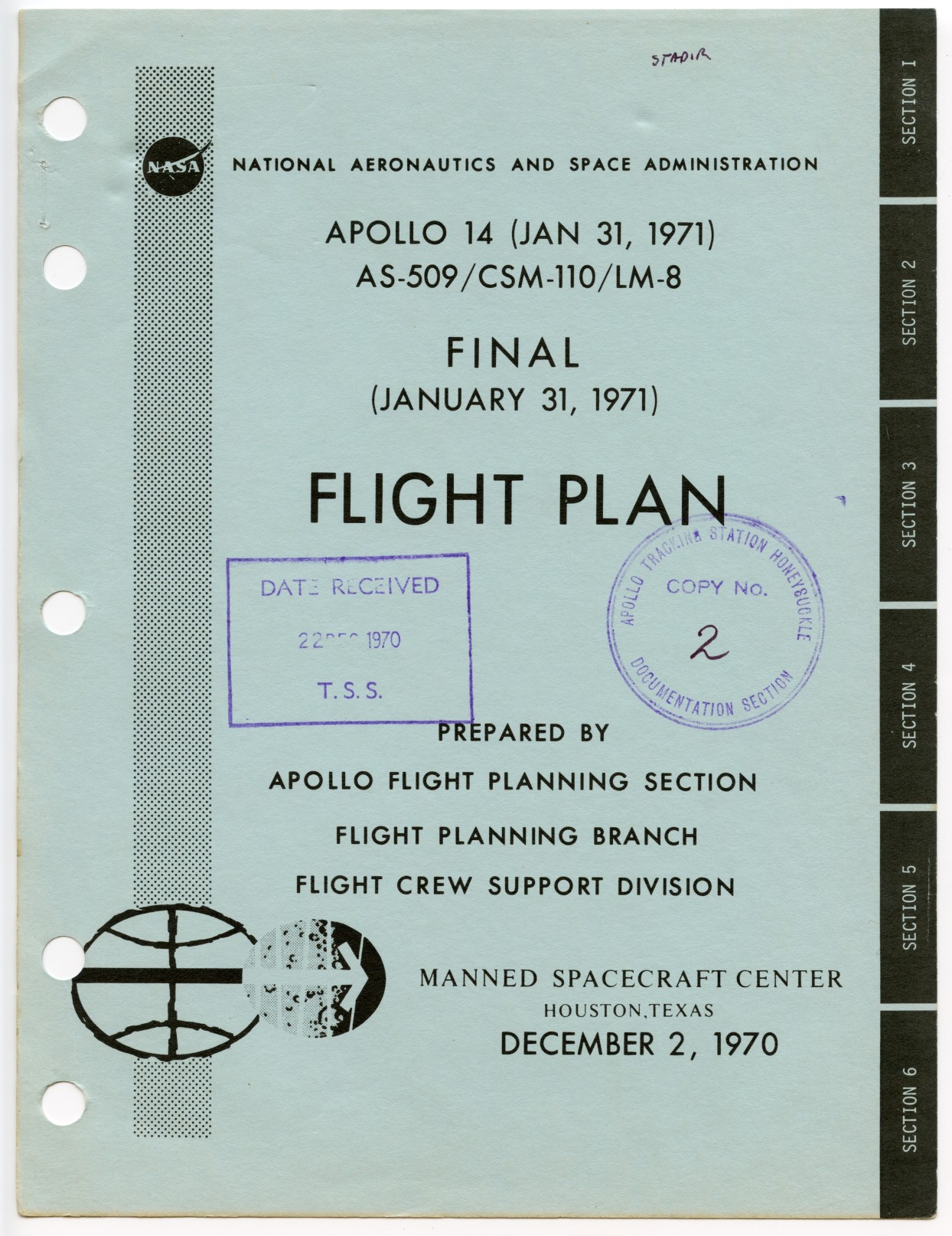
This Apollo 14 Flight Plan cover page is one of the many items of documentation handled by the TSS.
(See the complete Apollo 14 Flight Plan here.)
With thanks to Hamish Lindsay. Scan: Colin Mackellar.
|
During mission support times the Technical Support Section were responsible for the daily collection of all of the magnetic tapes, high speed printout, paper chart rolls and console TTY printouts. All such items were carefully labelled and packaged at the end of each operations shift for shipping to the GSFC archive.
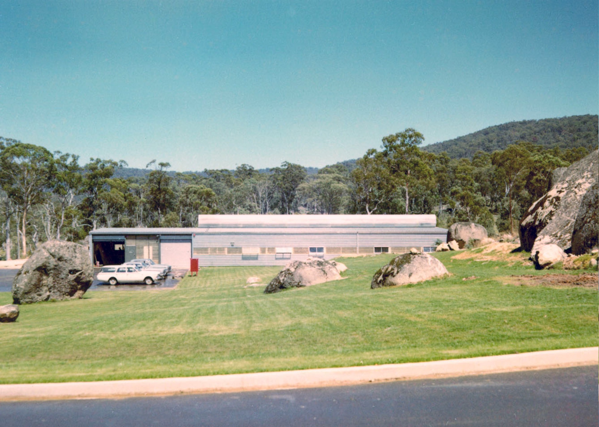
|
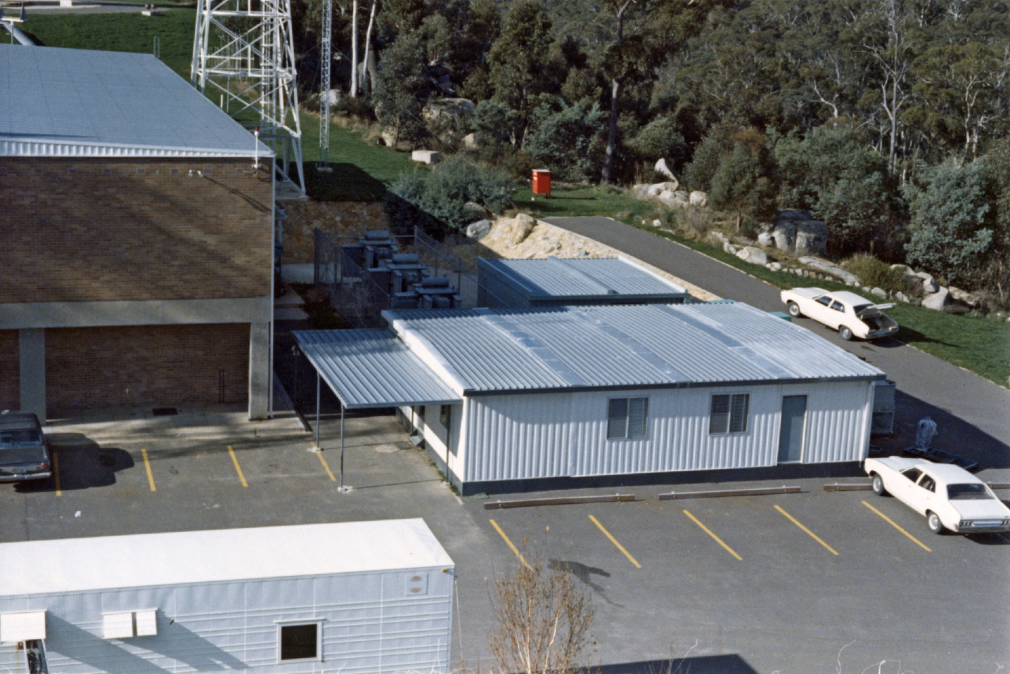
The TSS Building as seen from the Skylab UHF Command Antenna.
Photo courtesy Milton Turner. Scan: Colin Mackellar. |
|
Telemetry tapes at Honeysuckle during Apollo 16.
L-R: Mike Linney, Geoff Ruck, ? (partly obscured), Trevor Conyard.
From a Super 8 movie by Ed von Renouard. |
|
John Vanderkly (left) and Brian Hale stand amidst canisters of telemetry tapes not long after Apollo 17’s first EVA on Tuesday December 12, 1972. These all needed to be labelled, packed and shipped to Goddard.
Photo: Ed von Renouard. |
7.) FACILITIES SECTION
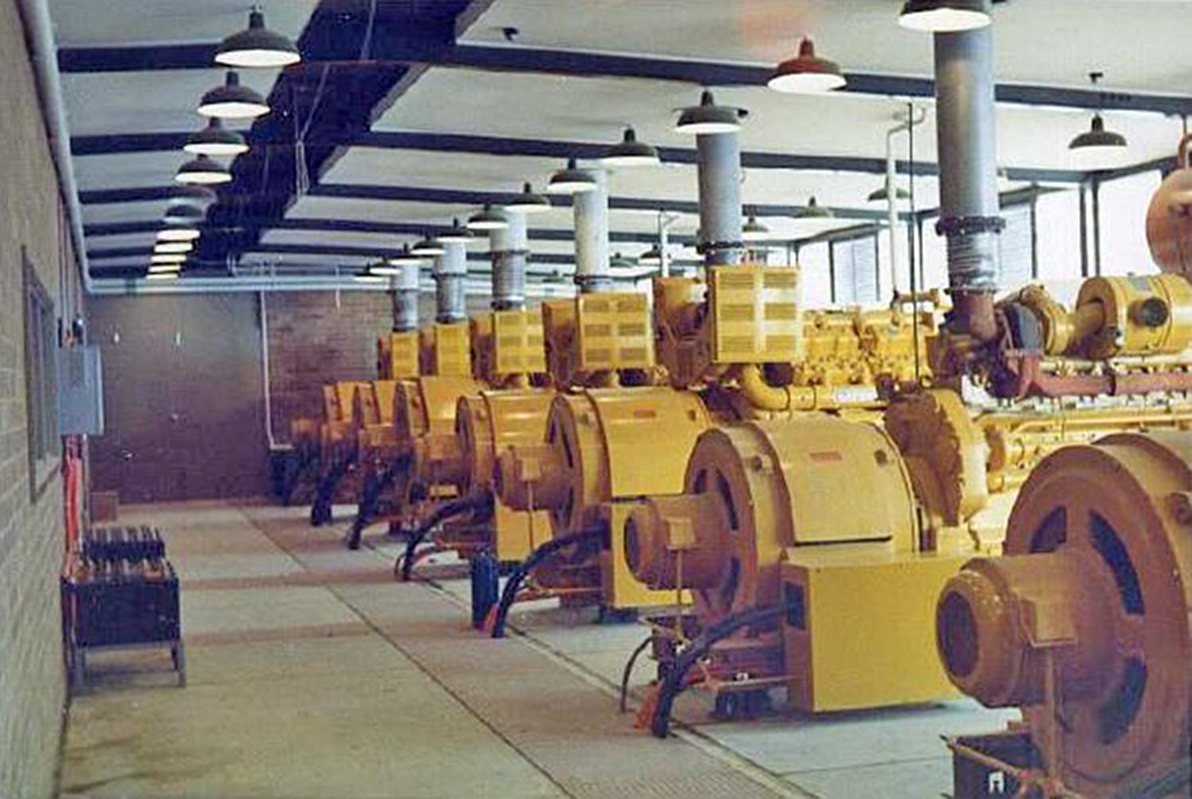
A separate building nearby provided all the station’s electric power. As it all had to be a standard 115 volt, 60 Hz mains for the American equipment, and due to the site remoteness, reliability of supply was paramount. All power was generated by a total of seven large diesel alternators ranging from 250 kVA to 500 kVA capacity, much more than double the stations maximum demand.
During Apollo 11 and subsequent missions all generators were brought on-line so as to ensure that the failure of any one would not impact the mission support.
Air conditioning was an essential requirement for the large array of electronic equipment in the operations areas. Cool air was delivered to the numerous equipment racks via an under floor plenum with the warm air extracted through ceiling vents. The plenum also provided a neat and tidy way of interconnecting the equipment racks with the many miles of assorted varieties of signal cabling.
Air conditioning units were housed in the basement along with other plant operating machinery, electrical control cabinets and rotary converters for the computers.
A separate electric power supply referred to as the ‘tech bus’ was provided for all of the mission critical operations equipment and supplied from separate generator(s) to the general lighting and power requirements of the rest of the building.
|
The Powerhouse – bank of diesel generators c. 1966.
Seven diesel alternators (generators) supplied more than enough electric power for the whole station.
The diesel engines were manufactured by Caterpillar with power capacities ranging from three 500 kVA units, two 350 kVA units and two 250 kVA units.
Photo: Ian Hahn. |
8.) LOGISTICS SECTION
The Logistics Section occupied a large area in the operations building and contained rows of storage racks housing a vast array of spare parts and replacement units.
The key to the logistics operation was the U.S. Federal Stock Numbering (FSN) system. Any individual small component, printed circuit board, sub/assembly, unit or complete chassis had a manufacture’s part number which had to be cross referenced to its unique FSN. It was the responsibility of the engineer or technician to look up the very thick FSN reference listings at the ‘service’ counter. The logistic officers (store men/women) were sometimes unreasonable and usually most emphatic: ‘no FSN, no part’, even if you could see it and point to it on the shelf.
Logistics often played an important roll in operations simulation exercises where staff were told that a discreet component in a certain piece of equipment had failed e.g. a printed circuit board or a computer memory module. The technician had to identify the part, determine its manufacturer part number, run down to the logistics counter, look up the FSN, convince the store man of the urgency without upsetting him, and get back to the operations area in the quickest time possible. NASA simulation observers noted response times as part of the stations evaluation report. Most of the operations staff soon became aware that a failure of his ‘part of kit’ could result in the failure of the mission or worse still, a loss of the astronauts.
During mission support times the Logistics Section were responsible for the daily collection of all of the magnetic tapes, high speed printout, paper chart rolls and console TTY printouts. All such items were carefully labeled and packaged at the end of each operations shift for shipping to the GSFC archive.
9.) ADMINISTRATION SECTION
Apart from the usual managerial, secretarial, and clerical support of the Administration staff, the Transport Officer played a most important and critical role in getting the staff to and from the station each day. The change-of-shift, particularly during mission operations, was a most challenging time as ten to twelve cars arrived and within half an hour they had to be refueled before the off-going shift drove them away again. There were four people to each car, carefully selected according to their residential locations close proximity.
Most cars in the fleet were identical and identified only by the last three digits on the number plate. Sometimes the daily transport list was changed, adjusted, rewritten and reissued in ‘real time’ right up to minutes before shift change times. The Transport Officer had to contend with sudden changes due to a late car arrival, a report of a vehicle problem, a vehicle accident, a procrastinating engineer authorizing last minute overtime, all without having a nervous breakdown.
When not coping with the chaotic demands of the daily list, the transport officer attended to fleet management tasks of vehicle repairs, registrations, accidents, insurance claims amongst other related paperwork.
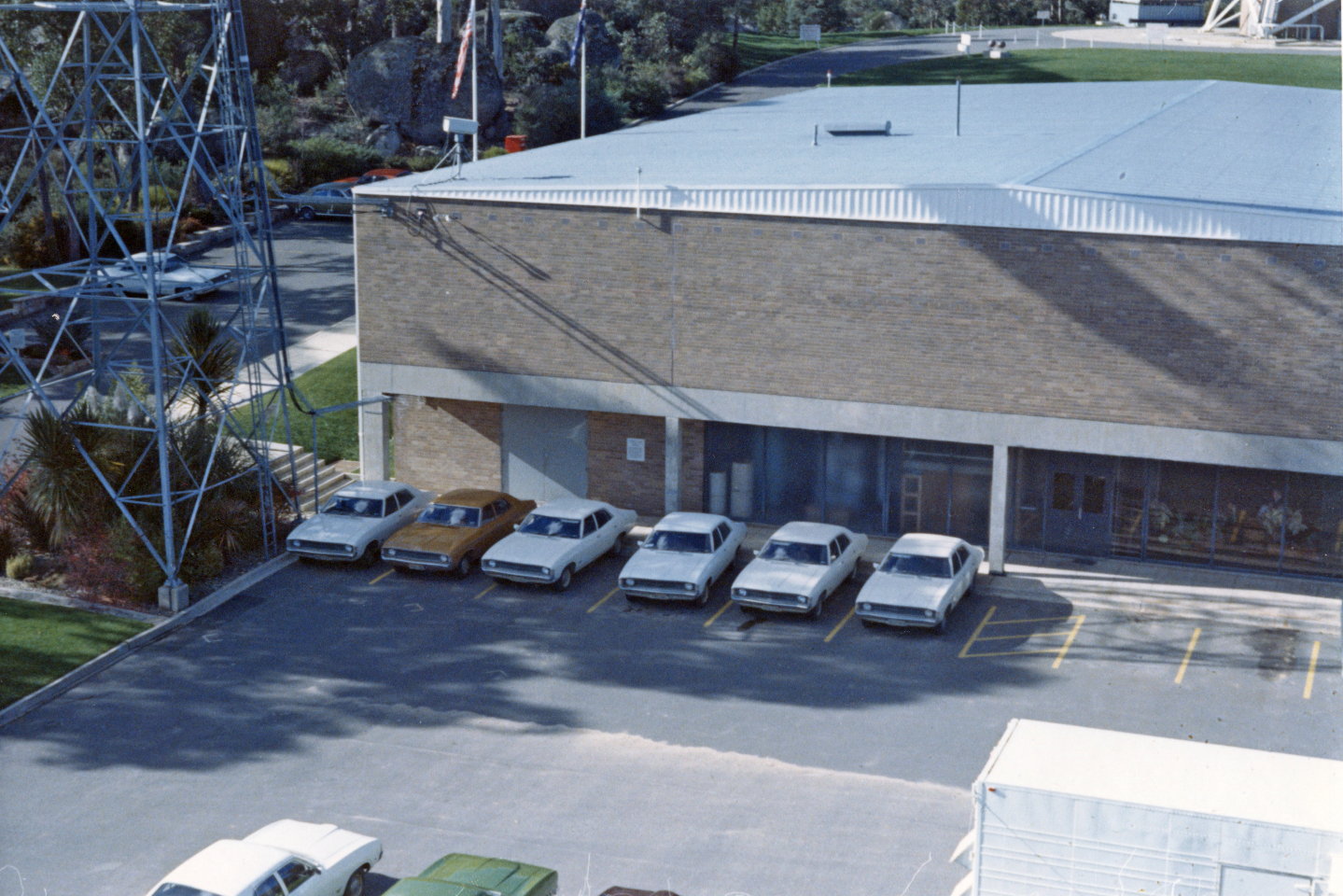
|
Part of the station car park, as seen from the Skylab UHF Command Antenna. The microwave link tower is at left, and the 26 metre USB antenna is off the top of the picture, behind the Operations Building.
Photo courtesy Milton Turner. Scan: Colin Mackellar. |
10.) THE CANTEEN
The canteen, as it was known, served many other functions besides being a cafeteria, tea room and crew room.
The large plate glass window looked out across the car park to a well manicured lawn in front of a native bush garden complemented by several large granite boulders several metres high. A spectacular backdrop vista of a eucalypt forest stretched many kilometers to the distant western mountain ridge.
|
The Powerhouse – as viewed from the car park at the western end of the Operations Building – is part of the view from just outside the canteen. |
Birthday morning teas, staff send off’s, training lectures, talks from many visiting dignitaries including NASA officials and even visiting astronauts were held in the canteen.
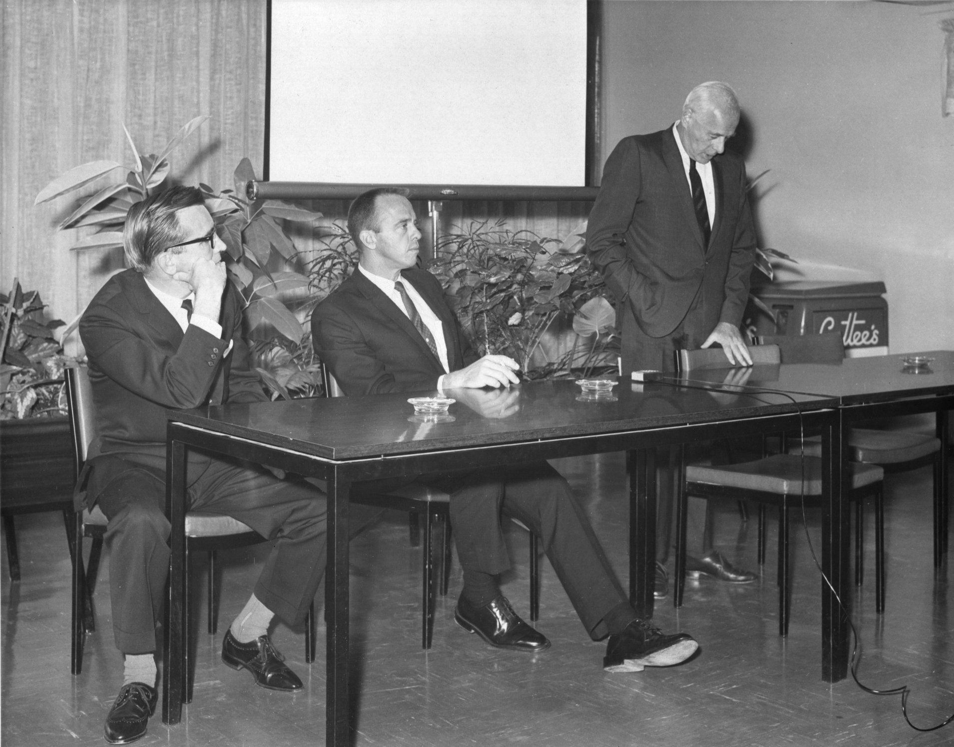
 |
In the canteen at Honeysuckle on 9th
September 1968 –
Station Director Tom Reid, Astronaut
Alan Shepard and Marshall Space Flight Center Director Eberhard Rees.
Note the Cottee’s soft drink vending machine at right.
Photo:
preserved by Mike Dinn, scan by Colin Mackellar. High res version. |
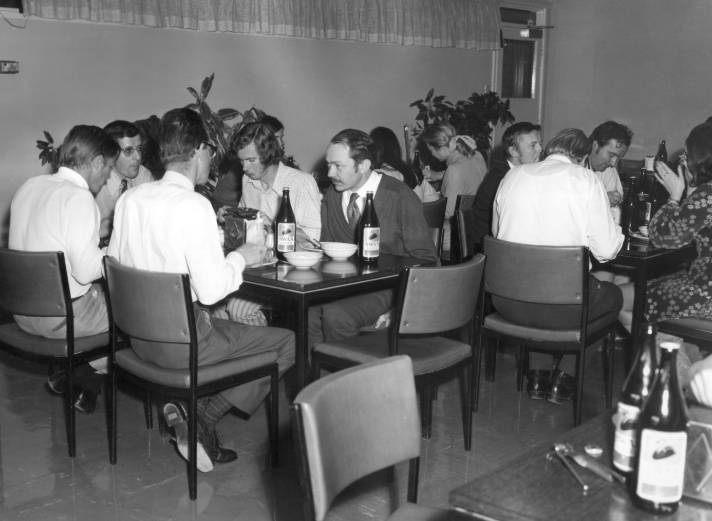
|
Lunch in the canteen after Apollo 16.
Swan beer courtesy of the Swan Brewery in Perth. (Story.)
Don Loughhead, Bryan Sullivan, Geoff Seymour, (1218 operator ??), Mike Evenett, Paula Denning?, Barbra Vanderput, John Saxon, John Vander Kly, Bob Riches, Lisa Jensen.
Photo: Hamish Lindsay(?), preserved by Milton Turner, scanned by Betty Saxon. |
The canteen was managed and operated by the delightful Betty and Horrie Clissold along with a small team of assistants. All meals were home made by Betty, whose baked dinners had all the trimmings from mint to cranberry sauce and gravies, just like grandma used to make. Mission splashdown lunches, Christmas lunches, fourth of July lunches were always sumptuous delights. During mission times meals were being prepared around the clock and the smell of bacon and eggs early in the morning after a busy night shift made the long tiring night well worth while.
Betty was like an auntie to all of the young blokes and made working at the station just like being at a country club, alpine resort or just a home away from home.
|
Horrie and Betty Clissold.
From Hamish Lindsay’s July 1969 staff photo. Scan: Colin Mackellar. |
PART B.) TRACKING OPERATIONS DESCRIPTION |
STATION READINESS TESTING
Prior to supporting tracking operations all Apollo stations performed a three hour station readiness test (SRT). This test was conducted in three phases.
Phase 1 tested the station intercom(munication) system where all operator positions were manned. Each operator’s headset/microphone was tested in a roll-call sequence.
Phase 2 testing involved alignment and calibration checking of all individual electronic units within each section as well as software diagnostic testing of the various computer peripheral devices.
Phase 3 involved the testing of integrated subsystems to verify the integrity of the station’s many data flow paths.
CADFISS TESTING
Following the SRT, the next major activity was the CADFISS (Computation And Data Flow of Integrated Sub-Systems) testing where the real-time CADFISS computers at the GSFC tested each tracking station in turn prior to handing them over to Mission Control. Using pre-recorded test tapes the station’s data flow paths of tracking, ranging, telemetry and command were thoroughly exercised and compared with known or predefined data values.
After the successful completion of CADFISS testing the station came under the control of the MCC at Houston when it entered a countdown of seventy minutes (H-70) to the initial acquisition of the spacecraft signal (AOS). The H-70 interface testing involved the MCC conducting a further series of data flow tests which were more aligned with the upcoming events or phase of the mission timeline. Specific telemetry data and biomedical formats, spacecraft commands and tracking data that were more closely tailored to give the flight controllers confidence that the station was correctly configured and ready to support the upcoming events in the mission flight plan. During the H-70 count extensive testing of the voice circuits switching (air/ground checks) were conducted to ensure the correct voice uplink paths through the station were correctly configured.
The time from the start of the SRT Phase 3 through to the end of the H-70 interface testing was one of the busiest and most activity intensive periods of Apollo tracking support.
FUNCTIONAL DATA PATHS
ANTENNA POINTING
The antenna pointing had to be extremely accurate due to the narrow beam width of the antenna, particularly at lunar distance. Also, it had to be able to rapidly ‘acquire’ the signal especially if the spacecraft was in low earth orbit.
To achieve this, the NASA computers at the Goddard Space Flight Center (GSFC) calculated and maintained an ephemeris of the spacecraft’s position, velocity and trajectory from tracking data previously received in real-time from other tracking stations. The spacecraft’s precise location for a given time within any station’s view period, or the precise acquisition of signal (AOS) time and horizon location was calculated and transmitted in the form of a fixed format teletype message to all supporting stations. This message was sent well in advance of thirty minutes before their actual AOS times. Such messages were referred to as ‘predicts’.
Each predict (TTY) message contained a tabulated block of numerical characters consisting of 29 lines. Each line represented the antenna X-angle, Y-angle and GMT time of a point along the spacecraft’s track or pass over the station.
This message was manually entered into the CP3 computer in the form of a punched paper tape. This was processed into an extrapolated series of antenna positions representing a stepped track of the spacecraft’s flight path across the sky for the station’s duration of view.
The output of the CP3 computer was in the form of a long five level teletype tape in a format compatible with the Antenna Position Programmer (APP) in the USB area which interfaced directly with the Antenna Servo System to drive the dish.
|
Frank Campbell loading a punched paper tape containing acquisition data at the Antenna Position Programmer (APP).
Photo HSK-5/9/7/2 - 18: Hamish Lindsay, 15 February 1967.
Scan: Colin Mackellar.
From Tom Reid’s album. Large, Larger. |
Once the spacecraft had been acquired using the predicted angles to precisely point the antenna, the normal procedure was to switch the antenna drive from Program track to Auto track where the receiver automatically ‘locked on’ and followed the spacecraft's radio frequency (RF) carrier signal.
For deeper space tracking operations the antenna remained in program track mode due to lower levels of the received signal strength. In such a tracking mode, pointing angles could be manually offset from the calculated angles to maximize the received signal strength.
Once the station had locked onto the carrier signal, another special purpose computer called a Tracking Data Processor (TDP) accepted the ranging data, the speed of the spacecraft relative to the station from the doppler determination, and the antenna angles relative to the station’s geographical location, and coded this information for transmission to the MCC in both a high-speed data format at 2.4 kBPS and also via low-speed teletype.
This data fed into the computers at the Real Time Computer Centers (RTCC) in both the GSFC and the MCC.
|
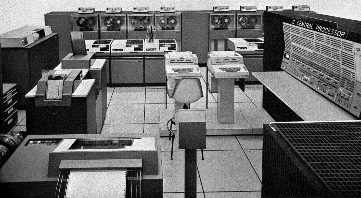
The RTCC at MCC Houston.
Computer: IBM Model 360 or 370.
Line Printer left foreground, Punch Card Reader center left, Line Printer left rear, eight Magnetic Tape Units at rear with four Disc Drive Units in front, two Operators Consoles in the centre.
Note the complexity of the Engineers Control Panel at centre right.
From the MCC-H Familiarization Manual, 1967. |
COMMAND PROCESSING
Commands consisted of instructions to the spacecraft subsystems, primarily to relieve the astronauts of routine housekeeping tasks. Examples were antenna switching for the optimum signal strength at the ground station, recorder control for transferring information stored on magnetic tape from the spacecraft to the ground, and the more important navigational data to update the command module and lunar module computers
All spacecraft commands were received by the station’s CMD computer via a NASCOM high-speed (4.8 kBPS) data line from the MCC.
Commands were usually sent in real time, however, in the event of a high-speed line failure, all command data could be received via teletype directly into the CMD computer using the hard wired Automatic Send/Receive TTY units. These TTY units could be patched directly to the low-speed incoming lines as they were fitted with a ‘blinding code’ unit which ignored normal TTY traffic and only passed the spacecraft command messages to the CMD computer. Alternatively the command data could be keyed into the CMD computer manually from the OPS2 position on the station operations console via the CAM keyboard.
The command data format from the MCC consisted of one or more data blocks of thirty binary bits, each block representing the actual command words. Each command word was followed by a further thirty binary bits representing a unique polynomial error protection (PEP) code, calculated specifically for each of the command words. The CMD computer calculated comparison PEP codes. If a PEP comparison error was encountered due to a NASCOM line drop-out or a noise glitch the whole of the MCC transmission sequence (command word plus each corresponding PEP code) would be ignored.
Upon receipt of a valid command data sequence the CMD computer passed the whole sequence to the Up Data Buffer (UBD) which sent it onto the appropriate PA in the USB area for transmission to the spacecraft after which the CMD computer wrote a record to the command history magnetic tape.
As the command data was transmitted out through the antenna a verification receiver in the waveguide detected the outgoing data and returned a ‘copy’ of it back to the UDB, where a digital bit by bit comparison was made to verify that valid command data had been transmitted to the spacecraft. At this point the CMD computer sent a command acceptance parameter (CAP) across the intercomputer channel where the TLM computer inserted it into the telemetry data stream being sent to the MCC via the NASCOM terrestrial high speed data lines.
When the spacecraft received and accepted the command data, it included a Message Acceptance Parameter (MAP) within the telemetry down-link data which the TLM computer also inserted into the telemetry data stream being sent to the MCC. The TLM computer also informed the CMD computer of the MAP via the intercomputer channel at which time the CMD computer wrote a further record to the command history magnetic tape.
In other words the MCC was assured that valid command data was received at the tracking station, that it was transmitted correctly from the station and that it was received and executed by the spacecraft.
TELEMETRY PROCESSING
The CM and LM spacecraft telemetry PCM bit streams from the demodulators in the USB area were processed by the four decommutators (DECOM) in the Telemetry Area. The data bit rates varied between normally high at 51.2 kBPS and low at 1.6 kBPS. The raw telemetry data, both wide band and narrow band, was recorded by reel-to-reel magnetic tape units.
|
Mincom M22 and M25 telemetry recorders.
Photo: Ian Hahn. |
The prime function of the DECOMs was to present all the received telemetry data to the TLM computer. They also allowed station personnel to monitor selected parameters on indicators or on (paper) chart recorders.
|
Jim Hanlon in the Telemetry area, at the patch panel of one of the Decoms.
Scan: Colin Mackellar.
From Tom Reid’s album, with thanks to John Saxon.
Large, Larger. |
On the CM spacecraft control panel (dashboard) there were vast numbers of dials, clocks, indicators, buttons and switches. All of these instrument measurements, dial readings, switch positions and indicator lights, approximately several hundred in total, were relayed in the telemetry data stream down to the tracking stations where they were recorded onto magnetic tape. The TLM computer stripped out the critical parameters into different formats as defined for each mission phase and transmitted them to the MCC
The Biomedical data was processed in several distinct paths. One path was used for the CM spacecraft when the biomed data came in the PCM telemetry stream. This was processed through the DECOMS and passed to the TLM computer Another path was used whenever the astronauts were either inside the LM, or outside the LM on the lunar surface in their space suits. For lunar surface operations the biomed data was normally relayed from the Portable Life Support Systems (PLSS or backpacks) through the LM spacecraft. All the LM biomed and life support data was routed down separate analog FM telemetry channels to the PAM processing equipment, which converted the analog information into digital data. All biomed data, along with the normal LM telemetry was passed to the TLM computer.
For the later Apollo missions the astronauts used a Lunar Rover Vehicle (LRV) to explore over greater distances from the LM. The LRV was fitted with a Lunar Communications Relay Unit (LCRU) which transmitted a separate down link signal to the ground tracking stations. Biomed data from the astronaut’s suits along with engineering data from the LRV was received and processed through the Analog Multiplexer Quantizer (AMQ) units and passed onto the TLM computer.
All of the Apollo telemetry information from the CM, LM or LRV systems including engineering, navigational and biomedical data was received by the TLM computer. The TLM computer processed and/or selected specific spacecraft parameters for insertion into the predefined data formats, depending on the particular mission phases, for transmission to the MCC via the terrestrial NASCOM high speed data lines.
END TO END DATA FLOW
The tracking stations provided a real time, two-way, high-speed connection between the Apollo Guidance Computer (AGC) in the spacecraft through the ground stations CMD/TLM computers, then onto the real time world-wide NASCOM network hub at the Goddard Space Flight Center in Greenbelt MD. and finally to the Real Time Computer Complex at the Mission Control Center in Houston, Texas. An extraordinary undertaking for the computing technologies of the late 1960s.
SYSTEMS FAULT HANDLING
The Apollo operational software, both the CMD and TLM systems were programmed such that whenever the operational software detected a hardware or software fault (glitch), the computer would immediately stop and perform a total core memory dump to magnetic tape which usually took about ten seconds. The tape then rewound and the computer automatically reloaded itself with the first core image version of the software which was written when the computer systems were first loaded and initialized after completion of the station’s site readiness testing (SRT).
During normal mission support, a situation could have existed where there might have been several core images (faults) already dumped to the tape. This condition would have delayed an automatic computer software reload/recovery for ‘many’ seconds while it ran down the tape looking for the next available clear space in which to write another core dump image.
For certain critical phases of a mission such a delay would have been unacceptable to MCC, therefore a ‘program jump’ switch allowed for certain software routines or segments, e.g. dumping to tape, to be manually bypassed without affecting other normal processing functions. Images of fault core dumps were far less of a priority at such mission critical phases. Each of the four military computers had three physical jump switches (J1, J2 & J3) for such purposes.
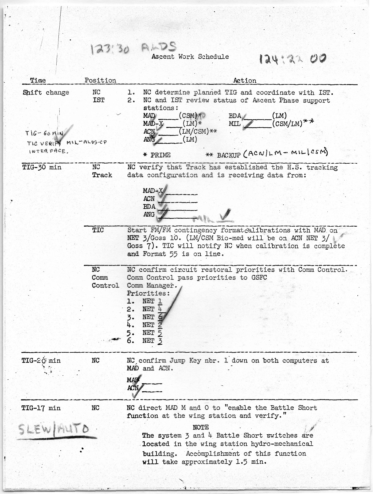
During Apollo 11, at twenty minutes prior to LM lift off from the moon the MCC requested both the Madrid and Ascension Island tracking stations to confirm that they had their computer Jump Key number 1 switch in the ‘down’ position.
|
This page from the Network Controller’s Ascent Work Schedule shows the call, at 20 minutes before liftoff, to confirm that the Jump Key Number 1 is down on both computers at Madrid and Ascension.
At T-17 minutes, the Battle Short function at the wing stations was enabled.
From Richard Stachurski’s NC Ascent Work Schedule. |
RECONFIGURATION
The standard configuration of the computers for tracking operations was normally CP1 for the CMD system and CP2 for the TLM system. Depending on the phase of the mission or the priorities of the CMD and TLM functions, the configuration could vary depending upon the number of stations supporting, the type and seriousness of a persistently intermittent hardware or software problem, or the estimated time to fix or to isolate the problem.
A reconfiguration or reversal of the CMD and TLM systems only required a rearrangement of the magnetic tapes onto different handlers and the changeover of the appropriate peripherals via the Type 1299 switch board.
VIDEO PROCESSING (Television)
The video signal, which was frequency modulated directly on to the S-Band carrier in the spacecraft, was received by the station via the 50 MHz FM subcarrier. It was demodulated by the SDDS and passed to the station’s video processing equipment located in the telemetry area.
The video signals from the spacecraft in the later Apollo missions complied with the American standard of 525-lines/60 field frame sequential colour television, and it also contained information on the television camera temperature and battery voltage.
The television signals were recorded on Ampex VR 660 and VR 1100 video recorders.
In Australia the composite processed television signal from the Honeysuckle Creek and/or Tidbinbilla stations were monitored on a modified Conrac colour monitor and transmitted to the specially prepared video centre in Sydney. The Parkes signal was sent directly to Sydney where NASA operators selected the best signal source for transmission direct to MCC, with a ‘split’ to the local Australian networks.
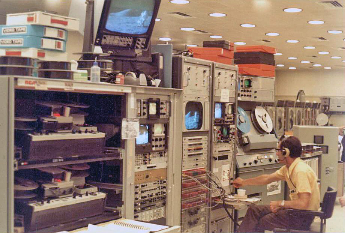
|
Honeysuckle Creek Test Equipment Supervisor Nevil Eyre in the video section during Apollo 17.
Note the two Ampex VR600 2-inch helical scan video-tape
recorders on the left and the older Ampex VR1100 on the right.
Polaroid photo scanned by Ed von Renouard. |
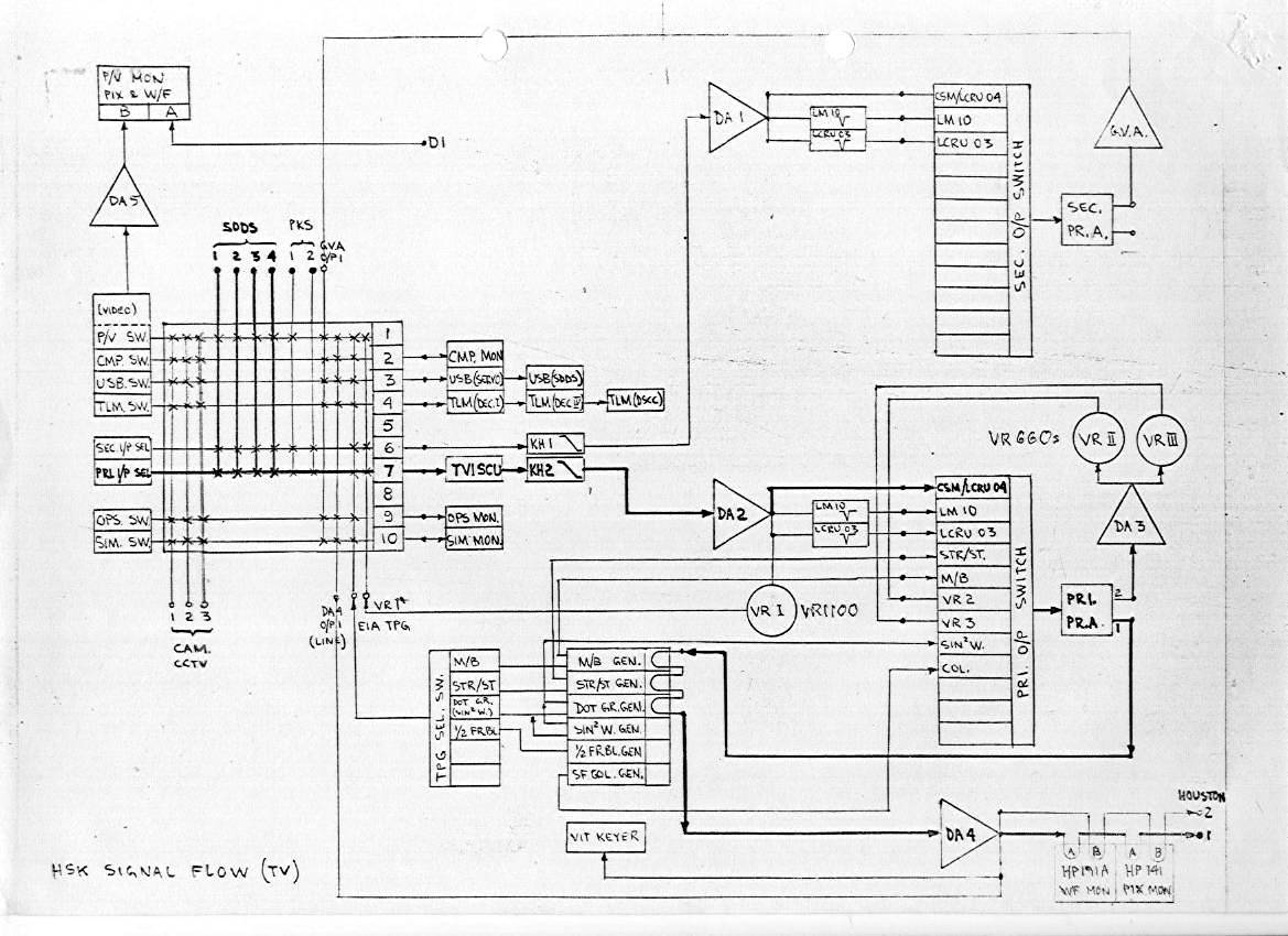
|
HSK TV Signal Flow. Diagram by Ed von Renouard.
|
(See also the Video section.)
References
1. Refer to NASCOM diagrams in the MSFN section.
2. NASA document SP-87, Proceedings of the Apollo Unified S-Band Technical Conference, Goddard Space Flight Center, July 14-14 1965.
3. Definition: A real time system is one in which the central processor is aware of external events as they occur and modifies its information and/or performs actions as a result of these events simultaneously with the events occurrence.
(Higher resolution scans of many of these photos are available.)