 |
|
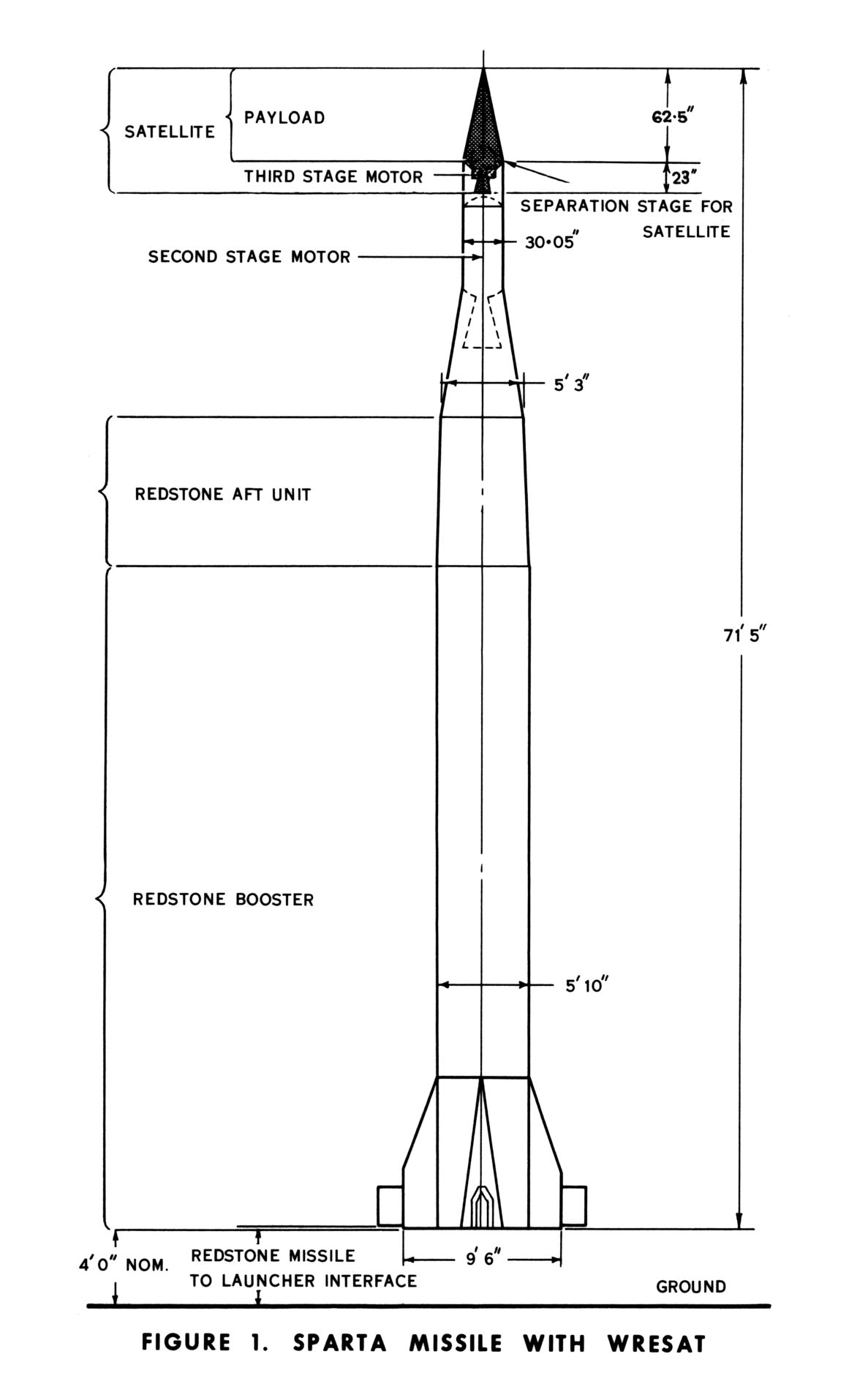
SPARTA Missile with WRESAT Diagram: WRE. |
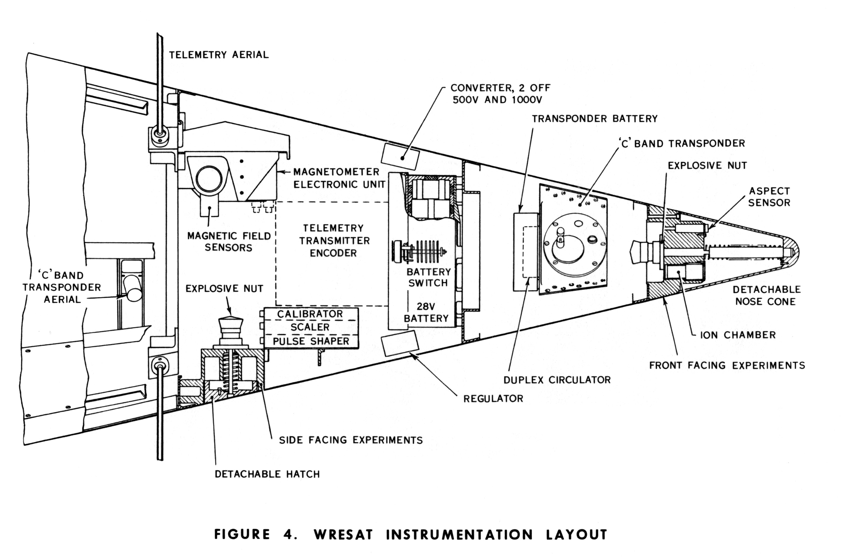 |
WRESAT Instrumentation Diagram: WRE. |
From the WRESAT booklet:
MEASUREMENTS TO BE MADE
The WRESAT experiment has been designed to provide information on the solar radiation flux in wavelengths which have a direct influence upon the temperature structure at heights above 30 km (19 miles), and will assist in the determination of the composition of the upper atmosphere above the homopause at approximately 100 km (62 miles). Direct measurement of the solar flux will provide data on solar activity.
In order to gain a better understanding of the relationship between the outer and inner layers of the atmosphere it is necessary to know the specific inputs from solar radiation. The thermal energy interchange between the outer and inner layers is influenced greatly by the presence and distribution of molecular oxygen and ozone and since these constituents affect the absorption of ultra-violet radiations measurements at ultra-violet wavelengths are essential inputs to a greater understanding of the physical processes taking place.
Specific measurements will be made at the following wavelengths –
(a) In the ultra-violet region of 1050 to 1660 Å by using ion chambers.
(b) In the wavelength around 2500 Å by the interference filter-photocell technique to determine absorption of ozone by the atmosphere.
(c) In the wavelengths of 1050 to 1340 Å by using an ion chamber with nitric oxide filling and a lithium fluoride window. This instrument will also be used as a telescope to determine the albedo of the earth in this waveband and to measure the resonantly scattered Lyman a (1216 Å) radiation from the geocoronal hydrogen belts.
(d) By using X-ray counter techniques, solar flux at 8 Å will be monitored.
These measurements will form inputs to three basic experiments –
(a) Sunset-sunrise experiment
(b) Orbital measurements in sunlight
(c) Orbital measurements towards the anti-solar point.
The sunrise-sunset experiment depends upon the viewing of the sun by the ion chambers and the ozone sensor through the atmosphere close to the earth. From this information, profiles of molecular oxygen and ozone concentration may be determined. It is a requirement that this experiment provide information at one latitude rather than cover a band of latitudes. Because the majority of telemetry stations are situated in the northern hemisphere, this experiment will be mainly confined to the high latitude northern stations in the U.K. and North America.
The orbital daylight experiment will provide measurements of solar flux in the ultra-violet and X-ray wavelengths. Solar activity will be monitored primarily by the X-ray sensor and these measurements will be correlated with the ionosonde soundings taken at Woomera, Salisbury and other world centres co-inciding with the satellite pass. The Lyman Alpha telescope will not be viewing the sun, but will measure the albedo of the earth in this wavelength.
The orbital night experiment will measure the Lyman Alpha radiation scattered resonantly by the geocoronal hydrogen. The Lyman Alpha telescope will also determine the position of Lyman Alpha sources in the night sky.
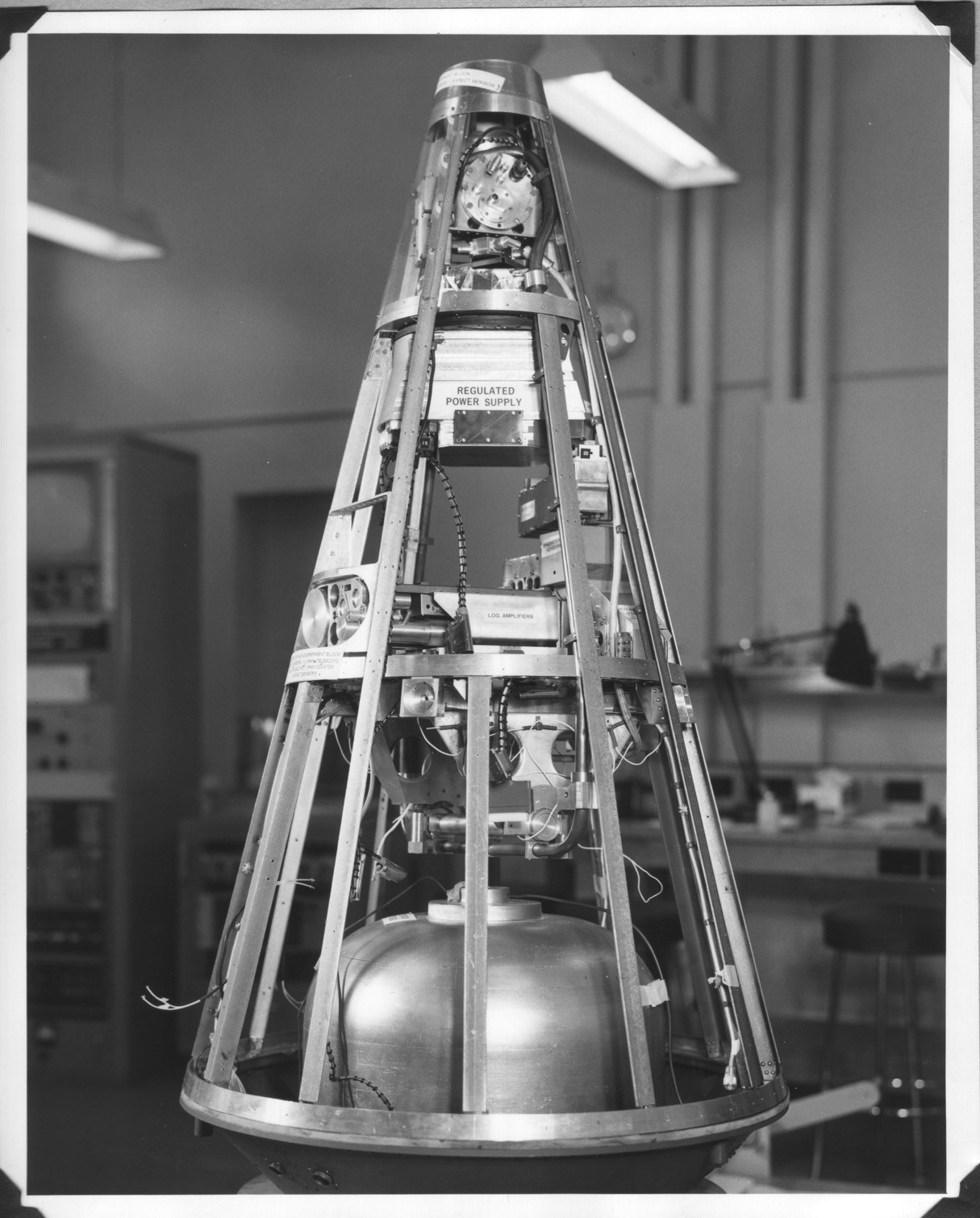
SATELLITE INSTRUMENTATION
The essential measurements of the experiment are made by a variety of sensors which are positioned either to look forward from the nose or sideways. The measurements are conveyed to the ground stations by radio-telemetry transmitting on 136.350 MHz. Additionally, the telemetry sender conveys certain satellite “house-keeping” information such as temperature and the state of charge of batteries. The radiation sensors are classified according to their response frequency. The ultra-violet ion chambers are –
| WINDOW | GAS | WAVELENGTH |
| Lithium fluoride | Nitric oxide | 1050 to 1340 Å |
| Sapphire | Xylene | 1425 to 1480 Å |
| Quartz | Triethylamine | 1560 to 1660 Å |
Measurements at wavelengths of 1050 to 1340 Å and 1425 to 1480 Å will complement and extend previous work done by Australia and USA in sounding rockets and also by the US. in satellites as far as is known. Measurements at 1560 to 1660 Å have not previously been made from satellite vehicles.
The X-ray counter will be collimated and have a mica window with gas filling of neon and argon. The response is of narrow width around 8 Å.
The solar aspect sensors are identical with those previously flown in Long Tom, (a W.R.E. Sounding Rocket) and rely upon the response of a photo-diode to the light collected from a flat teflon surface and a nipple of teflon. At night, the aspect will be determined by a magnetometer unit which will also provide attitude information during the daylight hours, provide a check upon the solar aspect sensors and determine the accuracy of attitude-prediction for night from the use of solar sensors only.
A magnetometer unit is installed in the satellite at least 1 inch from any conducting surface. The influence of any switch motor, the effect of any ferrous material in the satellite and the residual magnetism associated with the third- stage motor will be tested. The weight of the magnetometer unit (head + amplifier + leads) is about 3/4 lb.
The ozone sensor is a photodiode sensing the solar flux after transmission through an interference filter centred around 2500 A in the Hartley band. This experiment, although monitoring solar flux in these wavelengths, is dependent on measurements at sunrise or sunset for ozone profile determination.
The Lyman a telescope has a field of view of 2° half angle. With such a field of view, the sun will not be seen during daylight orbiting. The amplifier will be set for maximum sensitivity to measure the resonantly scattered Lyman a radiation (~10 -5 of daylight flux).
There are two positions of instrumentation in the satellite. The first position is located forward looking from the nose, the tip of which will be separated after injection, and comprises three ion chambers, the ozone sensor and aspect sensor.